Isuzu 4HK1-TC өрт сөндіру көлігінің қозғалтқышына техникалық қызмет көрсету нұсқаулығы, сондай-ақ қозғалтқышты жөндеу нұсқаулығы деп те аталады.
Isuzu өрт сөндіру машинасы
немесе инженерлік кітап
Isuzu өрт сөндіру көлігі
.
Isuzu өрт сөндіру көлігінің 4HK1-TC қозғалтқышы - өрт сөндіру көліктерінде кеңінен қолданылатын, сенімділігімен, беріктігімен және жоғары тиімділігімен танымал жоғары өнімді дизельді қозғалтқыш. Қозғалтқыштың ұзақ мерзімді тұрақты жұмысын қамтамасыз ету үшін үнемі техникалық қызмет көрсету және жөндеу қажет. Бұл мақалада техникалық қызмет көрсету персоналына жақсы түсінуге және жұмыс істеуге көмектесу үшін Isuzu өрт сөндіру көлігінің 4HK1-TC қозғалтқышына техникалық қызмет көрсету нұсқаулығының негізгі мазмұны қысқаша таныстырылады.
1. Қозғалтқышқа шолу
4HK1-TC қозғалтқышы - көлемі 5,2 литр және максималды қуаты 190 ат күші бар 4 цилиндрлі қатарлас турбокомпрессорлы дизельді қозғалтқыш. Қозғалтқыш отын тиімділігін арттыру және шығарындыларды азайту үшін кеңейтілген Common Rail отын бүрку жүйесін және электрондық басқару блогын (ECU) пайдаланады.
2. Күнделікті техникалық қызмет көрсету
Күнделікті техникалық қызмет көрсету қозғалтқыштың қалыпты жұмысын қамтамасыз етудің негізі болып табылады. Техникалық қызмет көрсету нұсқаулығында күнделікті тексеруге жататын элементтер егжей-тегжейлі көрсетілген, соның ішінде май мен салқындатқыш сұйықтық деңгейін тексеру, ауа сүзгісін тазалау немесе ауыстыру, отын сүзгісін ауыстыру және т.б. Сонымен қатар, нұсқаулықта қозғалтқыш майы мен май сүзгісін әдетте әр 5000 шақырым сайын немесе әр 6 ай сайын үнемі ауыстыру бойынша ұсыныстар берілген.
3. Ақаулық диагностикасы
Техникалық қызмет көрсету нұсқаулығында техникалық қызмет көрсету персоналына мәселелерді тез табуға және шешуге көмектесетін егжей-тегжейлі ақаулықтарды диагностикалау процесі бар. Нұсқаулықта жиі кездесетін ақаулық кодтары мен олардың мағыналары тізімделген және тиісті шешімдер ұсынылған. Мысалы, егер қозғалтқыштың қуаты жеткіліксіз болса, нұсқаулық техникалық қызмет көрсету персоналына отын жүйесін, турбокомпрессорды және шығару жүйесін және т.б. тексеруге нұсқау береді.
4. Күрделі жөндеу және бөлшектерді ауыстыру
Күрделі жөндеуді немесе бөлшектерін ауыстыруды қажет ететін қозғалтқыштар үшін техникалық қызмет көрсету нұсқаулығында егжей-тегжейлі қадамдар мен сақтық шаралары берілген. Мысалы, поршень сақиналары, клапан бағыттаушылары және мойынтіректер сияқты негізгі компоненттерді ауыстырған кезде, нұсқаулықта алып тастау және орнату қадамдары, сондай-ақ қажетті құралдар мен айналу моментінің сипаттамалары егжей-тегжейлі сипатталады.
5. Қауіпсіздік шаралары
Техникалық қызмет көрсету нұсқаулығында қауіпсіз жұмыс істеудің маңыздылығына ерекше назар аударылады. Кез келген техникалық қызмет көрсету жұмыстарын орындамас бұрын, қозғалтқыштың толығымен салқындатылғанына және қуат көзінің ажыратылғанына көз жеткізуіңіз керек. Сонымен қатар, нұсқаулықта қолғап, көзілдірік және қорғаныс киімдері сияқты жеке қорғаныс құралдарын пайдалану бойынша ұсыныстар берілген.
1A бөлім
Қозғалтқышты басқару жүйесі
Мазмұны
Бет
[if supportFields]> ТАЛДАУ \h \z \t "1A,1,1A-,2"
Қозғалтқышты басқару жүйесі
...
1A-
[if supportFields]> PAGEREF _Toc514492710 \h
4
[егер gte mso 9 болса]> 08D0C9EA79F9BACE118C8200AA004BA90B02000000080000000E0000005F0054006F006300350031003400340039003200370031003000000
[if supportFields]>
Сақтық шаралары
1A-
[if supportFields]> PAGEREF _Toc514492711 \h
4
[егер gte mso 9 болса]> 08D0C9EA79F9BACE118C8200AA004BA90B02000000080000000E0000005F0054006F0063003500310034003400390032003700310031000000
[if supportFields]>
Функциясы және жұмыс принципі
1A-
[if supportFields]> PAGEREF _Toc514492712 \h
5
[егер gte mso 9 болса]> 08D0C9EA79F9BACE118C8200AA004BA90B02000000080000000E0000005F0054006F0063003500310034003400390032003700310032000000
[if supportFields]>
Бөлшектердің конфигурация диаграммасы
.. 1A-
[if supportFields]> PAGEREF _Toc514492713 \h
21
[егер gte mso 9 болса]> 08D0C9EA79F9BACE118C8200AA004BA90B02000000080000000E0000005F0054006F0063003500310034003400390032003700310033000000
[if supportFields]>
Схема
.. 1A-
[if supportFields]> PAGEREF _Toc514492714 \h
25
[егер gte mso 9 болса]> 08D0C9EA79F9BACE118C8200AA004BA90B02000000080000000E0000005F0054006F0063003500310034003400390032003700310034000000
[if supportFields]>
Ақаулықты қалай анықтауға болады
1A-
[if supportFields]> PAGEREF _Toc514492715 \h
42
[егер gte mso 9 болса]> 08D0C9EA79F9BACE118C8200AA004BA90B02000000080000000E0000005F0054006F0063003500310034003400390032003700310035000000
[if supportFields]>
Ақаулық диагностикалық өлшегіш арқылы ақаулықтарды анықтау процедуралары
1A-
[if supportFields]> PAGEREF _Toc514492716 \h
48
[егер gte mso 9 болса]> 08D0C9EA79F9BACE118C8200AA004BA90B02000000080000000E0000005F0054006F0063003500310034003400390032003700310036000000
[if supportFields]>
Функционалды тексеруге шолу
.. 1A-
[if supportFields]> PAGEREF _Toc514492717 \h
50
[егер gte mso 9 болса]> 08D0C9EA79F9BACE118C8200AA004BA90B02000000080000000E0000005F0054006F0063003500310034003400390032003700310037000000
[if supportFields]>
Сұрау
1A-
[if supportFields]> PAGEREF _Toc514492718 \h
51
[егер gte mso 9 болса]> 08D0C9EA79F9BACE118C8200AA004BA90B02000000080000000E0000005F0054006F0063003500310034003400390032003700310038000000
[if supportFields]>
Қозғалтқышты басқару жүйесін тексеру
1A-
[if supportFields]> PAGEREF _Toc514492719 \h
53
[егер gte mso 9 болса]> 08D0C9EA79F9BACE118C8200AA004BA90B02000000080000000E0000005F0054006F0063003500310034003400390032003700310039000000
[if supportFields]>
Ақаулықтарды диагностикалау есептегішінің деректер тізімі
1A-
[if supportFields]> PAGEREF _Toc514492720 \h
55
[егер gte mso 9 болса]> 08D0C9EA79F9BACE118C8200AA004BA90B02000000080000000E0000005F0054006F006300350031003400340039003200370032003000000
[if supportFields]>
Ақаулықтарды диагностикалау есептегішінің деректер тізімінің мазмұны
1A-
[if supportFields]> PAGEREF _Toc514492721 \h
58
[егер gte mso 9 болса]> 08D0C9EA79F9BACE118C8200AA004BA90B02000000080000000E0000005F0054006F0063003500310034003400390032003700320031000000
[if supportFields]>
Ақаулық диагностикалық өлшеуіш шығысы
1A-
[if supportFields]> PAGEREF _Toc514492722 \h
64
[егер gte mso 9 болса]> 08D0C9EA79F9BACE118C8200AA004BA90B02000000080000000E0000005F0054006F006300350031003400340039003200370032003200000
[if supportFields]>
Ақаулық диагностикасы, есептегішті іске қосу сәтсіздігі
1A-
[if supportFields]> PAGEREF _Toc514492723 \h
65
[егер gte mso 9 болса]> 08D0C9EA79F9BACE118C8200AA004BA90B02000000080000000E0000005F0054006F0063003500310034003400390032003700320033000000
[if supportFields]>
Ақаулық диагностикалық есептегіш байланысының істен шығуы (анықтама)
1A-
[if supportFields]> PAGEREF _Toc514492724 \h
67
[егер gte mso 9 болса]> 08D0C9EA79F9BACE118C8200AA004BA90B02000000080000000E0000005F0054006F0063003500310034003400390032003700320034000000
[if supportFields]>
ECM-мен байланыс ақаулығы (анықтама)
1A-
[if supportFields]> PAGEREF _Toc514492725 \h
71
[егер gte mso 9 болса]> 08D0C9EA79F9BACE118C8200AA004BA90B02000000080000000E0000005F0054006F0063003500310034003400390032003700320035000000
[if supportFields]>
Жүйені іске қосуды растау
1A-
[if supportFields]> PAGEREF _Toc514492726 \h
74
[егер gte mso 9 болса]> 08D0C9EA79F9BACE118C8200AA004BA90B02000000080000000E0000005F0054006F0063003500310034003400390032003700320036000000
[if supportFields]>
Қозғалтқыштың MIL жарықтандыратын электр тізбегі жүйесін растау
1A-
[if supportFields]> PAGEREF _Toc514492727 \h
77
[егер gte mso 9 болса]> 08D0C9EA79F9BACE118C8200AA004BA90B02000000080000000E0000005F0054006F0063003500310034003400390032003700320037000000
[if supportFields]>
Қозғалтқыштың MIL жыпылықтайтын электр тізбегі жүйесінің растауы
1A-
[if supportFields]> PAGEREF _Toc514492728 \h
78
[егер gte mso 9 болса]> 08D0C9EA79F9BACE118C8200AA004BA90B02000000080000000E0000005F0054006F0063003500310034003400390032003700320038000000
[if supportFields]>
Шығарылған газды қайта айналымға енгізу (EGR) басқару жүйесін тексеру
1A-
[if supportFields]> PAGEREF _Toc514492729 \h
80
[егер gte mso 9 болса]> 08D0C9EA79F9BACE118C8200AA004BA90B02000000080000000E0000005F0054006F0063003500310034003400390032003700320039000000
[if supportFields]>
Жылытуды басқару жүйесін тексеру
1A-
[if supportFields]> PAGEREF _Toc514492730 \h
84
[егер gte mso 9 болса]> 08D0C9EA79F9BACE118C8200AA004BA90B02000000080000000E0000005F0054006F006300350031003400340039003200370033003000000
[if supportFields]>
Шығару тежегішін/ауа кірісін шектеуді басқару жүйесін тексеру
1A-
[if supportFields]> PAGEREF _Toc514492731 \h
87
[егер gte mso 9 болса]> 08D0C9EA79F9BACE118C8200AA004BA90B02000000080000000E0000005F0054006F0063003500310034003400390032003700330031000000
[if supportFields]>
Диагностикалық ақаулық кодына (DTC) шолу
.. 1A-
[if supportFields]> PAGEREF _Toc514492732 \h
92
[егер gte mso 9 болса]> 08D0C9EA79F9BACE118C8200AA004BA90B02000000080000000E0000005F0054006F0063003500310034003400390032003700330032000000
[if supportFields]>
DTC P0016 (Жылдам код 16)
1A-
[if supportFields]> PAGEREF _Toc514492733 \h
95
[егер gte mso 9 болса]> 08D0C9EA79F9BACE118C8200AA004BA90B02000000080000000E0000005F0054006F0063003500310034003400390032003700330033000000
[if supportFields]>
DTC P0087 (флэш-код 225)
1A-
[if supportFields]> PAGEREF _Toc514492734 \h
97
[егер gte mso 9 болса]> 08D0C9EA79F9BACE118C8200AA004BA90B02000000080000000E0000005F0054006F0063003500310034003400390032003700330034000000
[if supportFields]>
DTC P0088 (флэш-код 118)
1A-
[if supportFields]> PAGEREF _Toc514492735 \h
103
[егер gte mso 9 болса]> 08D0C9EA79F9BACE118C8200AA004BA90B02000000080000000E0000005F0054006F0063003500310034003400390032003700330035000000
[if supportFields]>
DTC P0089 (флэш-код 151)
1A-
[if supportFields]> PAGEREF _Toc514492736 \h
109
[егер gte mso 9 болса]> 08D0C9EA79F9BACE118C8200AA004BA90B02000000080000000E0000005F0054006F0063003500310034003400390032003700330036000000
[if supportFields]>
DTC P0091, P0092 (Жылдам код 247)
1A-
[if supportFields]> PAGEREF _Toc514492737 \h
112
[егер gte mso 9 болса]> 08D0C9EA79F9BACE118C8200AA004BA90B02000000080000000E0000005F0054006F0063003500310034003400390032003700330037000000
[if supportFields]>
DTC P0093 (227 флэш-код)
1A-
[if supportFields]> PAGEREF _Toc514492738 \h
116
[егер gte mso 9 болса]> 08D0C9EA79F9BACE118C8200AA004BA90B02000000080000000E0000005F0054006F0063003500310034003400390032003700330038000000
[if supportFields]>
DTC P0107, P0108 (Жылдам код 32)
1A-
[if supportFields]> PAGEREF _Toc514492739 \h
122
[егер gte mso 9 болса]> 08D0C9EA79F9BACE118C8200AA004BA90B02000000080000000E0000005F0054006F0063003500310034003400390032003700330039000000
[if supportFields]>
DTC P0112, P0113 (Жылдам код 22)
1A-
[if supportFields]> PAGEREF _Toc514492740 \h
127
[егер gte mso 9 болса]> 08D0C9EA79F9BACE118C8200AA004BA90B02000000080000000E0000005F0054006F006300350031003400340039003200370034003000000
[if supportFields]>
DTC P0117, P0118 (Жылдам код 23)
1A-
[if supportFields]> PAGEREF _Toc514492741 \h
132
[егер gte mso 9 болса]> 08D0C9EA79F9BACE118C8200AA004BA90B02000000080000000E0000005F0054006F0063003500310034003400390032003700340031000000
[if supportFields]>
DTC P0122, P0123 (Жылдам код 43)
1A-
[if supportFields]> PAGEREF _Toc514492742 \h
137
[егер gte mso 9 болса]> 08D0C9EA79F9BACE118C8200AA004BA90B02000000080000000E0000005F0054006F0063003500310034003400390032003700340032000000
[if supportFields]>
DTC P0182, P0183 (Жылдам код 211)
1A-
[if supportFields]> PAGEREF _Toc514492743 \h
142
[егер gte mso 9 болса]> 08D0C9EA79F9BACE118C8200AA004BA90B02000000080000000E0000005F0054006F0063003500310034003400390032003700340033000000
[if supportFields]>
DTC P0192, P0193 (Жылдам код 245)
1A-
[if supportFields]> PAGEREF _Toc514492744 \h
147
[егер gte mso 9 болса]> 08D0C9EA79F9BACE118C8200AA004BA90B02000000080000000E0000005F0054006F0063003500310034003400390032003700340034000000
[if supportFields]>
[if supportFields]>
DTC P0201, P0202, P0203, P0204 (Жылдам код 271,272,273,274)................................................ 1A-157
DTC P0217 (флэш-код 542)................................................................................................ 1A-170
DTC P0219 (флэш-код 543)................................................................................................ 1A-172
DTC P0234 (Жылдам код 42)................................................................................................. 1A-175
DTC P0299 (флэш-код 65)................................................................................................. 1A-178
DTC P0335 (Жылдам код 15)................................................................................................. 1A-182
DTC P0336 (Жылдам код 15)................................................................................................. 1A-187
DTC P0340 (Жылдам код 14).................................................................................................. 1A-190
DTC P0341 (Жылдам код 14)................................................................................................. 1A-195
DTC P0380 (Жылдам код 66)................................................................................................. 1A-198
DTC P0381 (Жылдам код 67).................................................................................................. 1A-201
DTC P0404 (Жылдам код 45)................................................................................................. 1A-205
DTC P0409 (Жылдам код 44)................................................................................................. 1A-208
DTC P0477, P0478 (Жылдам код 46)............................................................................................. 1A-212
DTC P0500 (Жылдам код 25).................................................................................................. 1A-216
DTC P0502, P0503 (Жылдам код 25)............................................................................................. 1A-218
DTC P0563 (Жылдам код 35)................................................................................................. 1A-223
DTC P0601 (Жылдам код 53).................................................................................................. 1A-225
DTC P0602 (Жылдам коды 154)................................................................................................ 1A-226
DTC P0604, P0606, P060B (Жылдам кодтар 153, 51, 36)................................................................. 1A-228
DTC P0641 (Жылдам код 55).................................................................................................. 1A-230
DTC P0650 (флэш-код 77)................................................................................................. 1A-233
DTC P0651 (Жылдам код 56)................................................................................................. 1A-237
DTC P0685, P0687 (Жылдам код 416).................................................................................................... 1A-241
DTC P0697 (Жылдам код 57)................................................................................................. 1A-245
DTC P1093 (Жылдам коды 227)................................................................................................ 1A-248
DTC P1261, P1262 (Жылдам код 34)............................................................................................. 1A-253
DTC P1404 (Жылдам код 45)................................................................................................. 1A-255
DTC P1621 (Жылдам код 54)................................................................................................. 1A-257
DTC P2122, P2123 (Жылдам код 121).................................................................................................... 1A-258
DTC P2127, P2128 (Жылдам код 122).................................................................................................... 1A-264
DTC P2138 (Жылдам код 124)................................................................................................ 1A-270
DTC P2146, P2149 (Жылдам код 158).................................................................................................... 1A-273
DTC P2228, P2229 (Жылдам код 71)............................................................................................. 1A-279
DTC P253A (Жылдам код 28)................................................................................................. 1A-284
DTC P256A (Жылдам код 31)................................................................................................. 1A-287
DTC U0073 (Жылдам код 84)................................................................................................. 1A-291
Симптомдарды диагностикалау................................................................................................................ 1A-296
Құбылыстар: Үзіліс....................................................................................................... 1A-297
Белгі: Қиын бастау......................................................................................................... 1A-300
Құбылыстар: Кернеудің күрт артуы, тұрақсыз бос жүріс немесе қозғалтқыштың тоқтап қалуы................................................................................ 1A-303
Құбылыстар: Бос жүріс жылдамдығының жоғары болуы................................................................................................... 1A-306
Белгі: Апаттық тоқтату................................................................................................... 1A-307
Белгі: Шұғыл ауыстыру......................................................................................................... 1A-309
Белгі: Қуаттың жеткіліксіздігі, үдеудің бұзылуы немесе жауаптың кешігуі.......................................................... 1A-311
Құбылыстар: Үзіліссіз жұмыс, үдеудің бұзылуы................................................................... 1A-314
Белгі: Жану шуылы................................................................................................... 1A-316
Белгі: Отынның үнемділігі төмен................................................................................... 1A-317
Құбылыстар: пайдаланылған газдан шығатын қара түтін................................................................................... 1A-319
Белгі: Шығарылған газдан ақ түтін................................................................................................ 1A-321
Негізгі сенсор параметрлері............................................................................................................ 1A-323
Арнайы құралдар............................................................................................................................ 1A-325
Бағдарлама................................................................................................................................. 1A-326
Бағдарламалау ережесі................................................................................................................ 1A-326
Бағдарлама................................................................................................................................. 1A-326
Инъекциялық сорғыны оқыту............................................................................................................ 1A-328
Реттеу............................................................................................................................ 1A-328
Қозғалтқышты басқару жүйесі
уақытша
Сақтық шаралары
Схеманы сынау құралдарын пайдалану
Диагностика бағдарламасына сәйкес диагноз қойылған жағдайда, басқаша көрсетілмесе, қуат беру жүйесінің электрлік диагностикасы үшін сынақ шамын пайдаланбаңыз. Егер зонд терминалы диагностикалық бағдарлама үшін пайдаланылатын болса, 5-8840-2835-0 терминалдық сынақ адаптері жинағын пайдаланыңыз.
Нарықта қолжетімді электрлік компонент
Нарықта қолжетімді электрлік компоненттер дегеніміз - көлік құралына орнату үшін нарықтан сатып алынған электрлік компоненттер. Бұл компоненттер көлік құралын жобалау кезеңінде ескерілмейтіндіктен, осы компоненттерді пайдаланған кезде оларға назар аударыңыз.
Сақтық шаралары:
Нарықта қолжетімді электрлік компоненттердің қуаты мен жерге қосуы электрлік басқару жүйесінің тізбегіне қатысы жоқ тізбекке қосылуы керек.
Нарықта қолжетімді электрлік компоненттерді пайдалануға болатын болса да, кейбір жағдайларда олар электр басқару жүйесінің функционалдық ақауына әкелуі мүмкін. Оған электр жүйесіне қосылмаған құрылғылар, мысалы, ұялы телефон, радио кіреді. Сондықтан, қозғалтқышты диагностикалау кезінде алдымен нарықта қолжетімді электрлік компоненттердің орнатылғанын тексеріңіз. Егер солай болса, оларды көліктен алып тастаңыз. Егер компонентті алып тастағаннан кейін де ақаулық сақталса, диагностиканың жалпы ағынын орындаңыз.
ESD салдарынан болған зақым
Электрлік басқару жүйесіндегі электрондық бөлшектер өте төмен кернеуде жұмыс істей алатындықтан, олар ЭҚК салдарынан оңай зақымдалады. Кейбір электрондық бөлшектер 100 В-тан төмен статикалық электр тогынан зақымдалады, бұл адам үшін байқалмайды. Адам үшін байқалмайтын ЭҚК 4000 В кернеуді қажет етеді. Көптеген жағдайларда адам статикалық электр тогын алып жүреді, бұл жағдайда үйкеліс пен индукциялық электрлендіру ең көп таралған.
●
Адам орындықта екі жаққа қозғалған кезде үйкеліс электрленуін тудырады.
● Оқшауланған аяқ киім киген адам электрлендірілген заттың жанында болған кезде, электростатикалық индукция адам жерге тиген сәтте пайда болады. Бірдей полярлықтағы зарядтар қарама-қарсы полярлықтағы зарядтармен кездескенде адам электрленеді. Статикалық электр зақым келтіретіндіктен, электрондық бөлшектерді мұқият өңдеп, оларды тексеріңіз.
Сақтық шаралары:
ЭСҚ салдарынан болатын зиянды болдырмау үшін келесі ережелерді сақтаңыз:
● ECM терминалының түйіспе түйреуіштеріне және ECM тізбегінің артқы тақтасына дәнекерленген электрондық бөлшектерге тимеңіз.
● Бөлшектерді орнатуға дайындық жұмыстары аяқталмайынша, парктерді ашпаңыз.
● Бөлшектерді қаптамадан шығармас бұрын, қаптаманы және көлік құралын жерге қосыңыз.
● Орындықта екі жаққа қозғалсаңыз, тұрып отырсаңыз немесе белгілі бір қашықтықта қозғалып жатқанда бөлшекті басқарсаңыз, бөлшекті орнатпас бұрын қалыпты жерге тиіп тұрғаныңызға көз жеткізіңіз.
Функциясы және жұмыс принципі
Қозғалтқышты басқару жүйесі (Common Rail)
Жүйеге шолу және оның егжей-тегжейлері
Қозғалтқышты басқару жүйесі дегеніміз - қозғалтқышты жүргізу жағдайына сәйкес оңтайлы жану күйіне дейін басқаруға арналған электрлік басқару жүйесі. Ол келесі бөліктерден тұрады:
● Электронды басқарылатын отын бүрку жүйесі (Common Rail түрі)
● EGR
Сонымен қатар, қозғалтқышты басқару жүйесі келесі жүйелік басқару функцияларын қамтиды.
● Жылытуды басқару жүйесі
● Қозғалтқыштың айналмалы шығысы
● Байланыс және өзін-өзі диагностикалау функциясы
[эндиф]
[if gte vml 1]>
[эндиф]
Электронды басқарылатын отын бүрку жүйесі (Common Rail түрі)
Common Rail жүйесі қысым камерасымен және инжектормен жабдықталған. Қысым камерасы қысымды отынды сақтауға арналған және Common Rail деп аталады; инжектор қысымды отынды жану камерасына айдау үшін электрондық басқару электромагниттік клапанымен жабдықталған. Инъекцияны басқару (инъекция қысымы, инъекция жылдамдығы және инъекция уақыты) ECM арқылы басқарылатындықтан, Common Rail жүйесі қозғалтқыш жылдамдығы мен жүктемесін тәуелсіз басқаруға мүмкіндік береді. Қозғалтқыш жылдамдығы төмен болса да, тұрақты инъекция қысымын сақтауға болады, бұл дизель қозғалтқышы іске қосылғанда және үдеуде қара түтіннің пайда болуын айтарлықтай азайтады. Бұл басқару арқылы пайдаланылған газ таза болады, пайдаланылған газ көлемі азаяды және шығыс жоғары болады.
Инъекция көлемін бақылау
Ол қозғалтқыш жылдамдығы мен газ педальын ашудан алынған сигналға сәйкес инжектор орамасын басқарады және ең жақсы көлемге жету үшін отын бүрку көлемін басқарады.
Инъекция қысымын бақылау
Қозғалтқыш жылдамдығы төмен болса да, жоғары қысымды бүркуді қамтамасыз ету үшін, жалпы рельстің ішіндегі отын қысымын бақылау керек. Қозғалтқыш жылдамдығы мен отын бүрку көлеміне сәйкес жалпы рельстегі тиісті қысымды есептеңіз, басқару сорғысы арқылы отынның тиісті мөлшерін шығарыңыз және оны қысыммен жалпы рельске беріңіз.
Инъекция уақытын бақылау
Ол уақыт функциясын ауыстырады және қозғалтқыш жылдамдығы мен бүрку көлеміне сәйкес тиісті отын бүрку уақытын есептейді, содан кейін инжекторды басқарады.
Инъекция жылдамдығын бақылау
Цилиндрдің жану тиімділігін арттыру үшін, тұтану үшін аздап отын бүркіңіз (алдын ала бүркіңіз). Тұтанғаннан кейін екінші рет бүркіңіз (негізгі бүркіңіз). Бүктеме уақытын және бүрку көлемін инжектор (инжектор катушкасы) арқылы басқарыңыз.
[эндиф]
[егер gte vml 1 болса]> +gs6VLdVdad08ISeCho1ZLN+whZ2jsTzgcsnJwldluLxNDiyagkxOquB2Knae/OLUsyEkjenmdzb mG/YhlRnCWPnb8C898bRJGtQvEOiVxjYhtLOxs8AySiT4JuDystlVV4WPeM6tK3VaILeDZxIOSsu ti/jidNGNZ3/J08yC1dNv9v8AAAA//8DAFBLAwQUAAYACAAAACEAarTA/8cEAAAAyAQAACwAAAF9y ZWxzLy5yZWxzhI/NCsIwEITvgu8Q9m7TehCRpr2I4FX0AdZk2wbbJGTj39ubi6AgeJtl2G9m6vYx jeJGka13CqqiBEFOe2Ndr+B03C3WIDihMzh6RwqexNA281l9oBFTfuLBBhaZ4ljBkFLYSMl6oAm5 8IFcdjofJ0z5jL0MqC/Yk1yW5UrGTwY0X0yxNwri3lQgjs+Qk/+zfddZTVuvrxO59CNCmoj3vCwj MfaUFOjRhrPHaN4Wv0VV5OYgm1p+LW1eAAAA//8DAFBLAwQUAAYACAAAACEAanXuCzqsDAADVCAAA HwAAAGNsaXBib2FyZC9kcmF3aW5ncy9kcmF3aW5nMS54bWzcVs1uGzcQvhfoOxC8y/vjXVkSsg5i JQoKuI5hJQ8w2uVqiXDJLUn9uei1PfRYoKdeei/6Bn2b1s/RIamVZaU/aJtTJWg1JIcfh998M9Kz 59tWkDXThitZ0OQspoTJUlVcLgv67u1sMKLEWJAVCCVZQXfM0OeXn37yDCZLDV3DS4II0kygoI21 3SSKTNmwFsyZ6pjEtVrpFiwO9TKqNGwQuRVRGsfDqAUu6eUj1EuwQFaa/wsoocr3rJqCXINBSFFO jmf2MYryvyPDRK5f627e3WoXeXmzvtWEVwVF5iS0SBGN9gt7NxxGJ7uWjwDbWrfOX9U12Rb0PBvm yTinZFfQfDRO8vM44LGtJSU6XOR5nOB6iQ7JKE1GOAgHNm/+BqJsXv01CIYZwkHjKETTuQDl+sM7 pxlGEm798P03Dz/89PDj1yQ9EOA2ELu9Uhh34hNtumtMlCFSTRuQS/ZCa7VpGFTGeQSmkNJwkmet P9Q4rMXmc1UhxbCyyuN9JPYOF4dJp419zVRLnFFQzUrrT4L1tbEhwN7FsWKU4NWMC+EHermYCk3W IAo686/9nZ64Cen5VG5bQAwzmGI8w625ZPs6+HKcpFl8lY4Hs+HoYpDNsnwwvohHgzgZX42HcTbO Xs6+cgEm2aThVcXkNZesr8kk+0DwLS+1Mqq2Z6VqI1QdL1lfl1iVSRyqkmwKOs7TPGTtTy8Z+9cf XbLllmkieFvQ0cEJJi7Xr2TlFWuBi2BHT8P3BYMc9N+eFcyR04Cjx27nXpJOWtXOzSzwG/WhFaYM CxEbmn2Dj1oovEcpeEdJo/T96ZzzQ4ZwhZINtrOCmi9WoBkl4jOJkkQo2xu6Nxa9AbLErQW1lARz anGEe1ad5ssGkYPopXqBeq35Xj4hVhe1MHZud4J5NvyNnMhBLLEVi1BF/r4aZwWWS0GZHLybY0e+ x+zEeNJ7pl3bRtPhsbpGuQadIjpYLonddayGEovmLW+ZITdsQ+5UC5KSDqQyuBCn+B7G53EeZ/hJ 0cpwlduymUHLhe802HEa0IZ5gn3ADI7Af/v5219/+e4JZoKYMWIl/fsEMz2CHCRp3zbMEerHDRkV hEx6AV1OVdsqSTRKECudGbPSjBgmjdKuWwfpeV8mq1vQcHfIwX0zmN6EHCRI1z9LwhQEX2j+hKiZ J90lIUO68HlC1DlO/B/If2TSFzYK3jF9qOGVYfPuDgUcemIocl/16Hjyg+637v+AuH8Nx+PL3wEA AP//AwBQSwMEFAAGAAgAAAAhAJxOXiHiBgAAOhwAABoAAABjbGlwYm9hcmQvdGhlbWUvdGhlbWUx LnhtbOxZT28bRRS/I/EdRntv4/+NozpV7NgNtGmj2C3qcbwe704zu7OaGSf1DbVHJCREQRyoxI0D Aiq1EpfyaQJFUKR+Bd7M7K534jVJ2wgqaA7x7tvfvP/vzZvdy1fuRQwdEiEpjzte9WLFQyT2+YTG Qce7NRpcWPeQVDieYMZj0vHmRHpXNt9/7zLe8BlNxhyLySgkEUHAKJYbuOOFsiUba2vSBzKWF3lC Yng25SLCCm5FsDYR+AgERGytVqm01iJMY28TOCrNqM/gX6ykJvhMDDUbgmIcgfSb0yn1icFODqoa IeeyxwQ6xKzjAc8JPxqRe8pDDEsFDzpexfx5a5uX1/BGuoipFWsL6wbmL12XLpgc1IxMEYxzodVB o31pO+dvAEwt4/r9fq9fzfkZAPZ9sNTqUuTZGKxXuxnPAsheLvPuVZqVhosv8K8v6dzudrvNdqqL ZWpA9rKxhF+vtBpbNQdvQBbfXMI3ulu9XsvBG5DFt5bwg0vtVsPFG1DIaHywhNYBHQxS7jlkytlO KXwd4OuVFL5AQTbk2aVFTHmsVuVahO9yMQCABjKsaIzUPCFT7ENO9nA0FhRrAXiD4MITS/LlEknL QtIXNFEd78MEx14B8vLZ9y+fPUHH958e3//p+MGD4/s/WkbOqh0cB8VVL7797M9HH6M/nnzz4uEX 5XhZxP/6wye//Px5ORDKZ2He8y8f//b08fOvPv39u4cl8C2Bx0X4iEZEohvkCO3zCAwzXnE1J2PxaitGIabFFVtxIHGMtZQS/n0VOugbc8zS6Dh6dInrwdsC2kcZ8OrsrqPwMBQzRUskXwsjB7jLOety UeqFa1pWwc2jWRyUCxezIm4f48My2T0cO/HtzxLom1laOob3QuKoucdwrHBAYqKQfsYPCCmx7g6l jl93qS+45FOF7lDUxbTUJSM6drJpsWiHRhCXeZnNEG/HN7u3UZezMqu3yaGLhKrArET5EWGOG6/i mcJRGcsRjljR4dexCsuUHM6FX8T1pYJIB4Rx1J8QKcvW3BRgbyHo1zB0rNKw77J55CKFogdlPK9j zovIbX7QC3GUlGGHNA6L2A/kAaQoRntclcF3uVsh+h7igOOV4b5NiRPu07vBLRo4Ki0SRD+ZiZJY XiXcyd/hnE0xMa0GmrrTqyMa/13jZhQ6t5Vwfo0bWuXzrx+V6P22tuwt2L3KambnRKNehTvZnntc TOjb35238SzeI1AQy1vUu+b8rjl7//nmvKqez78lL7owNGg9i9hB24zd0cqpe0oZG6o5I9elGbwl 7D2TARD1OnO6JPkpLANhUlcyCHBwgcBmDRJcfURVOAxxAkN71dNMApmyDiRKuITDoiGX8tZ4GPyV PWo29SHEdg6J1S6fWHJdk7OzRs7GaBWYA20mqK4ZnFVY/VLKFGx7HWFVrdSZpVWNaqYpOtJyk7WL zaEcXJ6bBsTcmzDUIBiFwMstON9r0XDYwYxMtN9tjLKwmCicZ4hkiCckjZG2ezlGVROkLFeWDNF2 2GTQB8dTvFaQ1tZs30DaWYJUFNdYIS6L3ptEKcvgRZSA28lyZHGxOFmMjjpeu1lresjHScebwjkZ LqMEoi71HIlZAG+YfCVs2p9azKbKF9FsZ4a5RVCFVx/W70sGO30gEVJtYxna1DCP0hRgsZZk9a81 wa3nZUBJNzqbFvV1SIZ/TQvwoxtaMp0SXxWDXaBo39nbtJXymSJiGE6O0JjNxD6G8OtUBXsmVMLr DtMR9A28m9PeNo/c5pwWXfGNmMFZOmZJiNN2q0s0q2QLNw0p18HcFdQD20p1N8a9uimm5M/JlGIa /89M0fsJvH2oT3QEfHjRKzDSldLxuFAhhy6UhNQfCBgcTO+AbIH3u/AYkgreSptfQQ71r605y8OU NRwi1T4NkKCwH6lQELIHbclk3ynMquneZVmylJHJqIK6MrFqj8khYSPdA1t6b/dQCKluuknaBgzu ZP6592kFjQM95BTrzelk+d5ra+CfnnxsMYNRbh82A03m/1zFfDxY7Kp2vVme7b1FQ/SDxZjVyKoC hBW2gnZa9q+pwitutbZjLVlca2bKQRSXLQZiPhAl8A4J6X+w/1HhM/sFQ2+oI74PvRXBxwvNDNIG svqCHTyQbpCWOIbByRJtMmlW1rXp6KS9lm3W5zzp5nJPOFtrdpZ4v6Kz8+HMFefU4nk6O/Ww42tL W+lqiOzJEgXSNDvImMCUfcnaxQkaB9WOB1+TIND34Aq+R3lAq2laTdPgCj4ywbBkvwx1vPQio8Bz S8kx9YxSzzCNjNLIKM2MAsNZ+g0mo7SgU+nPJvDZTv94KPtCAhNc+kUla6rO577NvwAAAP//AwBQ SwMEFAAGAAgAAAAhAJxmRkG7AAAAJAEAACoAAABjbGlwYm9hcmQvZHJhd2luZ3MvX3JlbHMvZHJh d2luZzEueG1sLnJlbHOEj80KwjAQhO+C7xD2btJ6EJEmvYjQq9QHCMk2LTY/JFHs2xvoRUHwsjCz 7DezTfuyM3liTJN3HGpaAUGnvJ6c4XDrL7sjkJSl03L2DjksmKAV201zxVnmcpTGKSRSKC5xGHMO J8aSGtHKRH1AVzaDj1bmIqNhQaq7NMj2VXVg8ZMB4otJOs0hdroG0i+hJP9n+2GYFJ69elh0+UcE y6UXFqCMBjMHSldnnTUtXYGJhn39Jt4AAAD//wMAUEsBAi0AFAAGAAgAAAAhALvlSJQFAQAAHgIA ABMAAAAAAAAAAAAAAAAFtDb250ZW50X1R5cGVzXS54bWxQSwECLQAUAAYACAAAACEArTA/ 8cEAAAAyAQAACwAAAAAAAAAAAAAAAAA2AQAAX3JlbHMvLnJlbHNQSwECLQAUAAYACAAAACEAnXuC zqsDAADVCAAAHwAAAAAAAAAAAAAAAAgAgAAY2xpcGJvYXJkL2RyYXdpbmdzL2RyYXdpbmcxLnht bFBLAQItABQABgAIAAAAIQCcTl4h4gYAADocAAAAAAAAAAAAAgYAADocAAAAAAAAAAAAaaaaaaaaaaaaaaaaaaaaaaaaaaaaaaaaaaaaaaa dGhlbWUvdGhlbWUxLnhtbFBLAQItABQABgAIAAAAIQCcZkZBuwAAACQBAAAqAAAAAAAAAAAAAA ACINAABjbGlwYm9hcmQvZHJhd2luZ3MvX3JlbHMvZHJhd2luZzEueG1sLnJlbHNQSwUGAAAAAAAUA BQBnAQAAJQ4AAAAA " stroked="f"> mso-position-vertical:absolute;mso-position-vertical-relative:text; mso-width-percent:0;mso-height-percent:200;mso-width-relative:margin; mso-height-relative:margin;v-text-anchor:top' o:gfxdata="UEsDBBQABgAIAAAAIQC75UiUBQEAAB4CAAATAAAW0NvbnRlbnRfVHlwZXNdLnhtbKSRvU7DMBSF dyTewfKKEqcMCKEmHfgZgaE8wMW+SSwc27JvS/v23KTJgkoXFsu+P+c7Ol5vDoMTe0zZBl/LVVlJ gV4HY31Xy4/tS3EvRSbwBlzwWMsjZrlprq/W22PELHjb51r2RPFBqax7HCCXIaLnThvSAMTP1KkI"> +gs6VLdVdad08ISeCho1ZLN+whZ2jsTzgcsnJwldluLxNDiyagkxOquB2Knae/OLUsyEkjenmdzb mG/YhlRnCWPnb8C898bRJGtQvEOiVxjYhtLOxs8AySiT4JuDystlVV4WPeM6tK3VaILeDZxIOSsu ti/jidNGNZ3/J08yC1dNv9v8AAAA//8DAFBLAwQUAAYACAAAACEAarTA/8cEAAAAyAQAACwAAAF9y ZWxzLy5yZWxzhI/NCsIwEITvgu8Q9m7TehCRpr2I4FX0AdZk2wbbJGTj39ubi6AgeJtl2G9m6vYx jeJGka13CqqiBEFOe2Ndr+B03C3WIDihMzh6RwqexNA281l9oBFTfuLBBhaZ4ljBkFLYSMl6oAm5 8IFcdjofJ0z5jL0MqC/Yk1yW5UrGTwY0X0yxNwri3lQgjs+Qk/+zfddZTVuvrxO59CNCmoj3vCwj MfaUFOjRhrPHaN4Wv0VV5OYgm1p+LW1eAAAA//8DAFBLAwQUAAYACAAAACEAvMmv16MDAADICAAA HwAAAGNsaXBib2FyZC9kcmF3aW5ncy9kcmF3aW5nMS54bWzcVsuO2zYU3RfoPxDce/SI5LGFaIKM EwUFJpPBOPkAmqIsNhSpkvRrim7bRZcFuuqm+6J/0L9p5zt6SVoej9MH2mZVG5b5uDy899xzr/30 2bYTaM204UqWODmLMWKSqprLZYnfva1GE4yMJbImQklW4h0z+NnFp588JcVSk77lFAGCNAUpcWtt X0SRoS3riDlTPZOw1yjdEQtTvYxqTTaA3IkojeNx1BEu8cUD1AtiCVpp/i+ghKLvWT0jck0MQApa HK/sfRT0vyOTQq5f6X7e32jnOb1e32jE6xIDc5J0QBGO9ht7M5hGJ6eWDwDbRnfOXjUN2kIG0jTP c8DalXg8jvNpnAc8trWIgsF0ksTnOUYUDJJJmkySvQFt3/wNBG1f/jUIuBncgcGRi6Z3Dsr1hzGn WTZEff/9N/c//HT/49coPRDgDiC7vVQuMJ9o019BogySatYSuWTPtVablpHaOIvAFFAabvKsDZca h7XYvFY1UExWVnm8j8TeIXBS9NrYV0x1yA1KrBm1/iayvjI2ODiYOFaMEryuuBB+opeLmdBoTUSJ K//ax/TITEjPp3LHAmJYgRTDHW7PJdvXwZfTJM3iy3Q6qsaT81FWZfloeh5PRnEyvZyO42yavai+ cg4mWdHyumbyiks21GSSfSD4jlOtjGrsGVVdBKrjlA11CVWZxKEq0Qaklqd5yNqfBhn71x8F2XHL NBK8K/HkYEQKl+uXsoawSWEJF2EcPXbfFwxwMHx7ViBHTgP+4HbuJemkVe/cygK+QR9aQcqgeKCh 2TfwaISCOKjgPUat0nena84OGIIdjDbQzkpsvlgRzTASn0mQJEDZYaCHwWIYEEnhaIktRmE4szCD M6te82ULyEH0Uj0HvTZ8L5/gq/NaGDu3O8E8Gz4iJ3IiltCKP18ZGwrJh6xhQ0DFlJjJ0bs5NOU7 SFAMl71n2nVuGDpI1jSg2CBVuIBYLpHd9awhFOrmLe+YQddsg25VRyRGPZHKwEacwnscP4nzOINP CiOo7J5b2lak48I3G2g6LdGGeY69z4wcgf/287e//vLdI8wEMGPASob3CWZ6BDmC1hcCpuYI9eO6 DCICJr2GLqoVEwhqEHTqGnRQm99jsr4hmtweOL9rR7PrwHkC9Pwz0mdE8IXmj4ipPMmO9AzogecJ MU9g4f9A9gOTvpZB447pQ9muDJv3tyDY0Aatr2tf6GB48hvuj+7/c7g/Csfzi98BAAD//wMAUEsD BBQABgAIAAAAIQCcTl4h4gYAADocAAAaAAAAY2xpcGJvYXJkL3RoZW1lL3RoZW1lMS54bWzsWU9v G0UUvyPxHUZ7b+P/jaM6VezYDbRpo9gt6nG8Hu9OM7uzmhkn9Q21RyQkREEcqMSNAwIqtRKX8mkC RVCkfgXezOyud+I1SdsIKmgO8e7b37z/782b3ctX7kUMHRIhKY87XvVixUMk9vmExkHHuzUaXFj3 kFQ4nmDGY9Lx5kR6Vzbff+8y3vAZTcYci8koJBFBwCiWG7jjhUolG2tr0gcylhd5QmJ4NuUiwgpu RbA2EfgIBERsrVaptNYiTGNvEzgqzajP4F+spCb4TAw1G4JiHIH0m9Mp9YnBTg6qGiHnsscEOsSs 4wHPCT8akXvKQwxLBQ86XsX8eWubl9fwRrqIqRVrC+sG5i9dly6YHNSMTBGMc6HVQaN9aTvnbwBM LeP6/X6vX835GQD2fbDU6lLk2RisV7sZzwLIXi7z7lWalYaLL/CvL+nc7na7zXaqi2VqQPaysYRf r7QaWzUHb0AW31zCN7pbvV7LwRuQxbeW8INL7VbDxRtQyGh8sITWAR0MUu45ZMrZTil8HeDrlRS+ QEE25NmlRUx5rFblWoTvcjEAgAYyrGiM1DwhU+xDTvZwNBYUawF4g+DCE0vy5RJJy0LSFzRRHe/D BMdeAfLy2fcvnz1Bx/efHt//6fjBg+P7P1pGzqodHAfFVS++/ezPRx+jP5588+LhF+V4WcT/+sMn v/z8eTkQymdh3vMvH//29PHzrz79/buHJfAtgcdF+IhGRKIb5Ajt8wgMM15xNSdj8WorRiGmxRVbcSBxjLWUEv59FTroG3PM0ug4enSJ68HbAtpHGfDq7K6j8DAUM0VLJF8LIwe4yznrclHqhWtaVsHN o1kclAsXsyJuH+PDMtk9HDvx7c8S6JtZWjqG90LiqLnHcKxwQGKikH7GDwgpse4OpY5fd6kvuORT he5Q1MW01CUjOnayabFoh0YQl3mZzRBvxze7t1GXszKrt8mhi4SqwKxE+RFhjhuv4pnCURnLEY5Y 0eHXsQrLlBzOhV/E9aWCSAeEcdSfECnL1twUYG8h6NcwdKzSsO+yeeQihaIHZTyvY86LyG1+0Atx lJRhhzQOi9gP5AGkKEZ7XJXBd7lbIfoe4oDjleG+TYkT7tO7wS0aOCotEkQ/mYmSWF4l3Mnf4ZxN MTGtBpq606sjGv9d42YUOreVcH6NG1rl868flej9trbsLdi9ympm50SjXoU72Z57XEzo29+dt/Es 3iNQEMtb1Lvm/K45e//55ryqns+/JS+6MDRoPYvYQduM3dHKqXtKGRuqOSPXpRm8Jew9kwEQ9Tpz uiT5KSwJ4VJXMghwcIHAZg0SXH1EVTgMcQJDe9XTDAKZsg4kSriEw6Ihl/LWeBj8lT1qNvUhxHYO idUun1hyXZOzs0bOxmgVmANtJqiuGZxVWP1SyhRsex1hVa3UmaVVjWqmKTrScpO1i82hHFyemwbE 3Jsw1CAYhcDLLTjfa9Fw2MGMTLTfbYyysJgonGeIZIgnJI2Rtns5RlUTpCxXlgzRdthk0AfHU7xW kNbWbN9A2lmCVBTXWCEui96bRCnL4EWUgNvJcmRxsThZjI46XrtZa3rIx0nHm8I5GS6jBKIu9RyJ WQBvmHwlbNqfWsymyhfRbGeGuUVQhVcf1u9LBjt9IBFSbWMZ2tQwj9IUYLGWZPWvNcGt52VASTc6 mxb1dUiGf00L8KMbWjKdEl8Vg12gaN/Z27SV8pkiYhhOjtCYzcQ+hvDrVAV7JlTC6w7TEfQNvJvT 3jaP3OacFl3xjZjBWTpmSYjTdqtLNKtkCzcNKdfB3BXUA9tKdTfGvboppuTPyZRiGv/PTNH7Cbx9 qE90BHx40Ssw0pXS8bhQIYculITUHwgYHEzvgGyB97vwGJIK3kqbX0EO9a+tOcvDlDUcItU+DZCg sB+pUBCyB23JZN8pzKrp3mVZspSRyaiCujKxao/JIWEj3QNbem/3UAipbrpJ2gYM7mT+ufdpBY0D PeQU683pZPnea2vgn558bDGDUW4fNgNN5v9cxXw8WOyqdr1Znu29RUP0g8WY1ciqAoQVtoJ2Wvav qcIrbrW2Yy1ZXGtmykEUly0GYj4QJfAOCel/sP9R4TP7BUNvqCO+D70VwccLzQzSBrL6gh08kG6Q ljiGwckSbTJpVta16eikvZZt1uc86eZyTzhba3aWeL+is/PhzBXn1OJ5Ojv1sONrS1vpaojsyRIF 0jQ7yJjAlH3J2sUJGgfVjgdfkyDQ9+AKvkd5QKtpWk3T4Ao+MsGwZL8Mdbz0IqPAc0vJMfWMUs8w jYzSyCjNjALDWfoNJqO0oFPpzybw2U7/eCj7QgITXPpFJWuqzue+zb8AAAD//wMAUEsDBBQABgAI AAAAIQCcZkZBuwAAACQBAAAqAAAY2xpcGJvYXJkL2RyYXdpbmdzL19yZWxzL2RyYXdpbmcxLnht bC5yZWxzhI/NCsIwEITvgu8Q9m7SehCRJr2I0KvUBwjJNi02PyRR7Nsb6EVB8LIws+w3s037sjN5 YkyTdxxqWgFBp7yenOFw6y+7I5CUpdNy9g45LJigFdtNc8VZ5nKUxikkUigucRhzDifGkhrRykR9 QFc2g49W5iKjYUGquzTI9lV1YPGTAeKLSTrNIXa6BtIvoST/Z/thmBSevXpYdPlHBMulFxagjAYz B0pXZ501LV2BiYZ9/SbeAAAAA//8DAFBLAQItABQABCAAAAAAAAAAAAAA4 AAAAAAAAAAAAABbQ29udGVudF9UeXBlc10ueG1sUEsBAi0AFAAGAAgAAAAhAK0wP/HBAAAAMgEA AAsAAAAAAAAAAAAAAANgEAAF9yZWxzLy5yZWxzUEsBAi0AFAAGAAArAAaaaaaaw AB8AAAAAAAAAAAAAAAAIAAGNsaXBib2FyZC9kcmF3aW5ncy9kcmF3aW5nMS54bWxQSwECLQAU AAYACAAAACEAnE5eIeIGAAAA6HAAAGgAAAAAAAAAAAAAAABgAAY2xpcGJAAAARo3 ZW1lMS54bWxQSwECLQAUAAYACAAAACEAanGZGQbsAAAAkAQAAKgAAAAAAAAAAAAAAAAaDQAAY2xp cGJvYXJkL2RyYXdpbmdzL19yZWxzL2RyYXdpbmcxLnhtbC5yZWxzUEsFBgAAAAAFAAUAZwEAAB0O AAAAAA== " stroked="f"> mso-position-vertical:absolute;mso-position-vertical-relative:text; mso-width-percent:0;mso-height-percent:0;mso-width-relative:margin; mso-height-relative:margin;v-text-anchor:top' o:gfxdata="UEsDBBQABgAIAAAAIQC75UiUBQEAAB4CAAATAAAW0NvbnRlbnRfVHlwZXNdLnhtbKSRvU7DMBSF dyTewfKKEqcMCKEmHfgZgaE8wMW+SSwc27JvS/v23KTJgkoXFsu+P+c7Ol5vDoMTe0zZBl/LVVlJ gV4HY31Xy4/tS3EvRSbwBlzwWMsjZrlprq/W22PELHjb51r2RPFBqax7HCCXIaLnThvSAMTP1KkI"> +gs6VLdVdad08ISeCho1ZLN+whZ2jsTzgcsnJwldluLxNDiyagkxOquB2Knae/OLUsyEkjenmdzb mG/YhlRnCWPnb8C898bRJGtQvEOiVxjYhtLOxs8AySiT4JuDystlVV4WPeM6tK3VaILeDZxIOSsu ti/jidNGNZ3/J08yC1dNv9v8AAAA//8DAFBLAwQUAAYACAAAACEAarTA/8cEAAAAyAQAACwAAAF9y ZWxzLy5yZWxzhI/NCsIwEITvgu8Q9m7TehCRpr2I4FX0AdZk2wbbJGTj39ubi6AgeJtl2G9m6vYx jeJGka13CqqiBEFOe2Ndr+B03C3WIDihMzh6RwqexNA281l9oBFTfuLBBhaZ4ljBkFLYSMl6oAm5 8IFcdjofJ0z5jL0MqC/Yk1yW5UrGTwY0X0yxNwri3lQgjs+Qk/+zfddZTVuvrxO59CNCmoj3vCwj MfaUFOjRhrPHaN4Wv0VV5OYgm1p+LW1eAAAA//8DAFBLAwQUAAYACAAAACEA0GPuCaADAADCCAAA HwAAAGNsaXBib2FyZC9kcmF3aW5ncy9kcmF3aW5nMS54bWzcVs2O2zYQvhfoOxC8e0Vp5R8J0QZZ Jw4CbDaLdfIANEVZTChSJem/LXptDz0W6KmX3ou+Qd+m3efokLK8Xqc/aJtTbVgecoYfZ775sZ88 3TYSrbmxQqsCx2cEI66YLoVaFvjd29lggpF1VJVUasULvOMWP734/LMnNF8a2taCIUBQNqcFrp1r 8yiyrOYNtWe65Qp0lTYNdbA0y6g0dAPIjYwSQkZRQ4XCFw9Qz6mjaGXEv4CSmn3g5ZSqNbUAKVl+ vLP3UbL/jkxztX5p2nl7Y7zn7Hp9Y5AoCwzMKdoARTjaK/ZmsIxOTi0fALaVaby9riq0LXA6Ssgk G2K0K/AkGY3HhHR4fOsQCwbkfAx6BgbxOCPjvZ7Vb/4GgdUv/hIDnOycAeHIQdt699T644iT9LyP +f77b+5/+On+x69RcgjfH0Bue6nB6zik2bZXkCaLlJ7WVC35M2P0pua0tN6i4wkI7W4KnPWXWo+1 2LzWJRBMV04HvE/D3SFumrfGupdcN8gLBTacuXARXV9Z1/nXm3hSrJainAkpw8IsF1Np0JrKAs/C ax/SIzOpAp3aH+sQux3IL9zhdT7ToQm+zOIkJZdJNpiNJuNBOkuHg2xMJgMSZ5fZiKRZ+nz2lXcw TvNalCVXV0LxviHj9KNqbwQz2urKnTHdRFBygvG+KaElY9K1JNoUOBsmwy5pfxokCa8/CrIRjhsk RQNFfDCiuU/1C1VC2DR3VMhOjh67H7oFOOi/AyuQI18C4eB2HirSV1a58zsL+IbyMBpSBl0I08y9 gUclNcTBpGgxqrW5O93zdsAQaDDawCwrsP1iRQ3HSL5SUJEA5XrB9MKiF6hicLTADqNOnDpYwZlV a8SyBuSu5pV+BuVaiX35dL56r6V1c7eTPLARIvI1TuUS5vD7lXVdH4WQDSgkNEyBuRq8m8NEvoME wWRAH7jxYxtED8mrCiq2K1W4gDqhkNu1vKIM2uataLhF13yDbnVDFUYtVdqCgiTwHpFzMiQpfBKQ UtAKx+oZbYT0kwZ+BlhNjeWB4+Azp0fgv/387a+/fPcIMwZMAlhx/z7BTI4gB3HSDw57hPppXYYi AiZDDV28Uu+BKm38aO5KLSi4Km+oobcHwu/qwfS6IzwGbv4Z41MqxcKIR6zMAsOe8RS4gecJK+ew 8X9g+oHJ0MhQ4J7pQ8+uLJ+3t5CCbga60NShy8Hw5Nc7HN3/2/B/EY7XF78DAAD//wMAUEsDBBQA BgAIAAAAIQCcTl4h4gYAADocAAAaAAAAY2xpcGJvYXJkL3RoZW1lL3RoZW1lMS54bWzsWU9vG0UU vyPxHUZ7b+P/jaM6VezYDbRpo9gt6nG8Hu9OM7uzmhkn9Q21RyQkREEcqMSNAwIqtRKX8mkCRVCk fgXezOyud+I1SdsIKmgO8e7b37z/782b3ctX7kUMHRIhKY87XvVixUMk9vmExkHHuzUaXFj3kFQ4 nmDGY9Lx5kR6Vzbff+8y3vAZTcYci8koJBFBwCiWG7jjhUolG2tr0gcylhd5QmJ4NuUiwgpuRbA2 EfgIBERsrVaptNYiTGNvEzgqzajP4F+spCb4TAw1G4JiHIH0m9Mp9YnBTg6qGiHnsscEOsSs4wHP CT8akXvKQwxLBQ86XsX8eWubl9fwRrqIqRVrC+sG5i9dly6YHNSMTBGMc6HVQaN9aTvnbwBMLeP6 /X6vX835GQD2fbDU6lLk2RisV7sZzwLIXi7z7lWalYaLL/CvL+nc7na7zXaqi2VqQPaysYRfr7Qa WzUHb0AW31zCN7pbvV7LwRuQxbeW8INL7VbDxRtQyGh8sITWAR0MUu45ZMrZTil8HeDrlRS+QEE2 5NmlRUx5rFblWoTvcjEAgAYyrGiM1DwhU+xDTvZwNBYUawF4g+DCE0vy5RJJy0LSFzRRHe/DBMde AfLy2fcvnz1Bx/efHt//6fjBg+P7P1pGzqodHAfFVS++/ezPRx+jP5588+LhF+V4WcT/+sMnv/z8 eTkQymdh3vMvH//29PHzrz79/buHJfAtgcdF+IhGRKIb5Ajt8wgMM15xNSdj8WorRiGmxRVbcSBxjLWUEv59FTroG3PM0ug4enSJ68HbAtpHGfDq7K6j8DAUM0VLJF8LIwe4yznrclHqhWtaVsHNo1kc lAsXsyJuH+PDMtk9HDvx7c8S6JtZWjqG90LiqLnHcKxwQGKikH7GDwgpse4OpY5fd6kvuORThe5Q 1MW01CUjOnayabFoh0YQl3mZzRBvxze7t1GXszKrt8mhi4SqwKxE+RFhjhuv4pnCURnLEY5Y0eHX sQrLlBzOhV/E9aWCSAeEcdSfECnL1twUYG8h6NcwdKzSsO+yeeQihaIHZTyvY86LyG1+0AtxlJRh hzQOi9gP5AGkKEZ7XJXBd7lbIfoe4oDjleG+TYkT7tO7wS0aOCotEkQ/mYmSWF4l3Mnf4ZxNMTGt Bpq606sjGv9d42YUOreVcH6NG1rl868flej9trbsLdi9ympm50SjXoU72Z57XEzo29+dt/Es3iNQ EMtb1Lvm/K45e//55ryqns+/JS+6MDRoPYvYQduM3dHKqXtKGRuqOSPXpRm8Jew9kwEQ9TpzuiT5 KSwJ4VJXMghwcIHAZg0SXH1EVTgMcQJDe9XTDAKZsg4kSriEw6Ihl/LWeBj8lT1qNvUhxHYOidUu n1hyXZOzs0bOxmgVmANtJqiuGZxVWP1SyhRsex1hVa3UmaVVjWqmKTrScpO1i82hHFyemwbE3Jsw 1CAYhcDLLTjfa9Fw2MGMTLTfbYyysJgonGeIZIgnJI2Rtns5RlUTpCxXlgzRdthk0AfHU7xWkNbW bN9A2lmCVBTXWCEui96bRCnL4EWUgNvJcmRxsThZjI46XrtZa3rIx0nHm8I5GS6jBKIu9RyJWQBv mHwlbNqfWsymyhfRbGeGuUVQhVcf1u9LBjt9IBFSbWMZ2tQwj9IUYLGWZPWvNcGt52VASTc6mxb1 dUiGf00L8KMbWjKdEl8Vg12gaN/Z27SV8pkiYhhOjtCYzcQ+hvDrVAV7JlTC6w7TEfQNvJvT3jaP 3OacFl3xjZjBWTpmSYjTdqtLNKtkCzcNKdfB3BXUA9tKdTfGvboppuTPyZRiGv/PTNH7Cbx9qE90 BHx40Ssw0pXS8bhQIYculITUHwgYHEzvgGyB97vwGJIK3kqbX0EO9a+tOcvDlDUcItU+DZCgsB+p UBCyB23JZN8pzKrp3mVZspSRyaiCujKxao/JIWEj3QNbem/3UAipbrpJ2gYM7mT+ufdpBY0DPeQU 683pZPnea2vgn558bDGDUW4fNgNN5v9cxXw8WOyqdr1Znu29RUP0g8WY1ciqAoQVtoJ2WvavqcIr brW2Yy1ZXGtmykEUly0GYj4QJfAOCel/sP9R4TP7BUNvqCO+D70VwccLzQzSBrL6gh08kG6QljiG wckSbTJpVta16eikvZZt1uc86eZyTzhba3aWeL+is/PhzBXn1OJ5Ojv1sONrS1vpaojsyRIF0jQ7 yJjAlH3J2sUJGgfVjgdfkyDQ9+AKvkd5QKtpWk3T4Ao+MsGwZL8Mdbz0IqPAc0vJMfWMUs8wjYzS yCjNjALDWfoNJqO0oFPpzybw2U7/eCj7QgITXPpFJWuqzue+zb8AAAD//wMAUEsDBBQABgAIAAAA IQCcZkZBuwAAACQBAAAqAAAY2xpcGJvYXJkL2RyYXdpbmdzL19yZWxzL2RyYXdpbmcxLnhtbC5y ZWxzhI/NCsIwEITvgu8Q9m7SehCRJr2I0KvUBwjJNi02PyRR7Nsb6EVB8LIws+w3s037sjN5YkyT dxxqWgFBp7yenOFw6y+7I5CUpdNy9g45LJigFdtNc8VZ5nKUxikkUigucRhzDifGkhrRykR9QFc2 g49W5iKjYUGquzTI9lV1YPGTAeKLSTrNIXa6BtIvoST/Z/thmBSevXpYdPlHBMulFxagjAYzB0pX Z501LV2BiYZ9/SbeAAAA//8DAFBLAQItABQABg5AIAAAiAAAAAAAAAAAQ7 AAAAAAAAABbQ29udGVudF9UeXBlc10ueG1sUEsBAi0AFAAGAAgAAAAhAK0wP/HBAAAAMgEAAAsA AAAAAAAAAAAAAANgEAAF9yZWxzLy5yZWxzUEsBAi0AFAAGAAgAAAAhANABAw7 AAAAAAAAAAAAAAIAIAAGNsaXBib2FyZC9kcmF3aW5ncy9kcmF3aW5nMS54bWxQSwECLQAUAAYA CAAAACEAnE5eIeIGAAAA6HAAAGgAAAAAAAAAAAAAAAA9BQAAY2xpcGJvAYA1Ro3ALAZA1W MS54bWxQSwECLQAUAAYACAAAACEAnGZGQbsAAAAkAQAAKgAAAAAAAAAAAAAAAXDQAAY2xpcGJv YXJkL2RyYXdpbmdzL19yZWxzL2RyYXdpbmcxLnhtbC5UEFAOAAAAAAAAAAAAAAAAAA AA== " stroked="f">
[егер gte vml 1 болса]>
[эндиф]
 [эндиф]
Отын жүйесі
Common Rail жүйесі екі отын қысымы жүйесінен тұрады.
● Төмен қысымды кіріс құбыры: отын багымен және айдау сорғысы арасында
● Жоғары қысымды желі: айдау сорғысы мен инжектор арасында
Отын отын багынан айдау сорғысына сорылып, жалпы рельске беру үшін сорғыда күшейтіледі. Осы кезде,
ECM сигналы Common Rail жүйесіне берілетін отын көлемін басқару үшін сору клапанын (Common Rail қысым реттегіші) басқарады.
Отын жүйесінің диаграммасы
[егер gte vml 1 болса]>
[эндиф]
|
Кілт
1. Жалпы теміржол
2. Қысымды шектейтін клапан
3. Инжектордың қайтару құбыры
4. Инжектор
5. Отын қайтару құбыры
6. Отын беру құбыры
|
7. Жанармай багісі
8. Тыныс алу клапаны
9. Стартер сорғысы
10. Отын сүзгісі (май-су бөлгішімен)
11. Қайтару клапаны
12.
Отын бүрку сорғысы
|
EGR
(Шығарылған газды қайта айналымға енгізу)
Egr жүйесі пайдаланылған газдың бір бөлігін қабылдау коллекторына қайта өңдейді және нәтижесінде азот оксидтерінің (NOx) шығарындыларын азайтады. EGR жүйесі арқылы жүргізудің жұмыс істеу қабілетін және пайдаланылған газ шығарындыларын азайтуға болады. EGR-ден шығатын басқару тогы соленоидты клапанның жұмыс істеуін басқарады және нәтижесінде EGR клапанының көтерілуін басқарады. Сонымен қатар, бұл жүйе EGR-ді дәл басқару үшін EGR позициясының сенсорымен нақты клапанның көтерілуін анықтайды.
EGR қозғалтқыш жылдамдығы, қозғалтқыштың салқындатқыш сұйықтығының температурасы, кіріс температурасы және атмосфералық қысым шарттары орындалған кезде жұмыс істей бастайды. Содан кейін ол қозғалтқыш жылдамдығы мен мақсатты отын бүрку көлеміне сәйкес клапанның ашылуын есептейді. Есептелген клапанның ашылуына сүйене отырып, ол соленоидты клапанның жетек жүктемесін анықтайды, содан кейін клапанды басқарады. EGR жұмысы кезінде ауа кіріс дроссельі жабылады, бұл кіріс коллекторының ішкі қысымының мақсатты мәнге жетуіне мүмкіндік береді.
[егер gte vml 1 болса]> mso-position-vertical:absolute;mso-position-vertical-relative:text; mso-width-percent:0;mso-height-percent:0;mso-width-relative:margin; mso-height-relative:margin;v-text-anchor:top' o:gfxdata="UEsDBBQABgAIAAAAIQC75UiUBQEAAB4CAAATAAAW0NvbnRlbnRfVHlwZXNdLnhtbKSRvU7DMBSF dyTewfKKEqcMCKEmHfgZgaE8wMW+SSwc27JvS/v23KTJgkoXFsu+P+c7Ol5vDoMTe0zZBl/LVVlJ gV4HY31Xy4/tS3EvRSbwBlzwWMsjZrlprq/W22PELHjb51r2RPFBqax7HCCXIaLnThvSAMTP1KkI"> +gs6VLdVdad08ISeCho1ZLN+whZ2jsTzgcsnJwldluLxNDiyagkxOquB2Knae/OLUsyEkjenmdzb mG/YhlRnCWPnb8C898bRJGtQvEOiVxjYhtLOxs8AySiT4JuDystlVV4WPeM6tK3VaILeDZxIOSsu ti/jidNGNZ3/J08yC1dNv9v8AAAA//8DAFBLAwQUAAYACAAAACEAarTA/8cEAAAAyAQAACwAAAF9y ZWxzLy5yZWxzhI/NCsIwEITvgu8Q9m7TehCRpr2I4FX0AdZk2wbbJGTj39ubi6AgeJtl2G9m6vYx jeJGka13CqqiBEFOe2Ndr+B03C3WIDihMzh6RwqexNA281l9oBFTfuLBBhaZ4ljBkFLYSMl6oAm5 8IFcdjofJ0z5jL0MqC/Yk1yW5UrGTwY0X0yxNwri3lQgjs+Qk/+zfddZTVuvrxO59CNCmoj3vCwj MfaUFOjRhrPHaN4Wv0VV5OYgm1p+LW1eAAAA//8DAFBLAwQUAAYACAAAACEALqpBQLwDAAD1CAAA HwAAAGNsaXBib2FyZC9kcmF3aW5ncy9kcmF3aW5nMS54bWzcVs1uGzcQvhfoOxC8y/vjlSwJWQex YgUFHMewkgcYcblaNlxyS1J/LnptDz0W6KmX3ou8Qd4m8XN0yNXKstIftM2pEiQNyeHHmY/fzOrJ 000tyYobK7TKaXISU8IV04VQi5y+eT3tDSmxDlQBUiue0y239On5l188gfHCQFMJRhBB2THktHKu GUeRZRWvwZ7ohitcK7WpweHQLKLCwBqRaxmlcTyIahCKnj9APQcHZGnEv4CSmr3lxQTUCixCSjY+ nNnFKNl/R4axWr0wzay5MT5ydr26MUQUOUXmFNRIEY12Czs3HEZHuxYPAJvS1N5flyXZ5DRNT9M4 7VOyzenZKB2lWb/F4xtHGDoMkjTJ8CyGDkn/LBvGu/OqV3+DwKrLv8TAINtg0DgI0DY+PLX6NOM0 zbqc73/+4f6X3+5//Z6k+/T9BuI2FxqjTsI12+YKr8kSpScVqAV/ZoxeVxwK6z1anpDQ9qTAWXeo 9Vjz9UtdIMGwdDrgfR7u9nnDuDHWveC6Jt7IqeHMhYNgdWVdG1/n4kmxWopiKqQMA7OYT6QhK5A5 nYbXLqVHblIForXf1iK2M3i/eIZf8zcdiuDbUZJm8UU66k0Hw7NeNs36vdFZPOzFyehiNIizUfZ8 +p0PMMnGlSgKrq6E4l1BJtknaq8FM9rq0p0wXUcoOcF4V5RYkkncliRZ53TURxWGvP40yTi8/ijJ WjhuiBR1Tod7Jxj7q75UBaYNYwdCtnb0OPxQLchB9xtYwTvyEggbN7OgSK+sYutn5viL8jAarwwr A7uZe4VfpdSYB5OioaTS5u54zvshQ7hCyRp7WU7tN0swnBL5lUJFIpTrDNZ884AxXBrTh0lrTlx OMI9y8aIRYXIreaVfoZyLcVOPm2sPmpp3cxtJQ9shIy8xkEusA9/vbSt8KSaNcx724bdONuKK0ni UPRIym4drR07gSKDQBILLKdc9d7MsIPf4YXiJvKWG9/m0fSgvCxR4a20EQucUMRtG14CwzJ7LWpu yTVfk1tdg6KkAaUtLsTYoeJBfBr34ww/KVrYCBrhWDWFWkjfmfCxwSowloc7CTlyOAD/+O7HD+9/ eoSZIGaMWEn3PsJMDyB7Sdo1GnuA+nlDRlaRSU+UO79UC19aUkPhu3mrzrDGVXEDbm73nN9Vvcl1 y3mC9Pwz0icgxdyIR8RMA8me9Azpwe8jYk5x4v9A9gOTofaxJjzT+zJfWj5rblGwbdt0oQ+gh39A RUcP/LB19wfF/6s4HJ//DgAA//8DAFBLAwQUAAYACAAACEAnE5eIeIGAA6HAAAGgAAAGNsaXBi b2FyZC90aGVtZS90aGVtZTEueG1s7FlPbxtFFL8j8R1Ge2/j/42jOlXs2A20aaPYLepxvB7vTjO7 s5oZJ/UNtUckJERBHKjEjQMCKrUSl/JpAkVQpH4F3szsrnfiNUnbCCpoDvHu29+8/+/Nm93LV+5F DB0SISmPO171YsVDJPb5hMZBx7s1GlxY95BUOJ5gxmPS8eZEelc233/vMt7wGU3GHIvJKCQRQcAo lhu444VKJRtra9IHMpYXeUJieDblIsIKbkWwNhH4CAREbK1WqbTWIkxjbxM4Ks2oz+BfrKQm+EwM NRuCYhyB9JvTKfWJwU4Oqhoh57LHBDrErOMBzwk/GpF7ykMMSwUPOl7F/Hlrm5fX8Ea6iKkVawvr BuYvXZcumBzUjEwRjHOh1UGjfWk7528ATC3j+v1+r1/N+RkA9n2w1OpS5NkYrFe7Gc8CyF4u8+5V mpWGiy/wry/p3O52u812qotlakD2srGEX6+0Gls1B29AFt9cwje6W71ey8EbkMW3lvCDS+1Ww8Ub UMhofLCE1gEdDFLuOWTK2U4pfB3g65UUvkBBNutZpUVMeaxW5VqE73IxAIAGMqxojNQ8IVPsQ072 cDQWFGsBeIPgwhNL8uUSSctC0hc0UR3vwwTHXgHy8tn3L589Qcf3nx7f/+n4wYPj+z9aRs6qHRwH xVUvvv3sz0cfoz+efPPi4RfleFnE//rDJ7/8/Hk5EMpnYd7zLx//9vTx868+/f27hyXwLYHHRfiIRkSiG+QI7fMIDDNecTUnY/FqK0YhpsUVW3EgcYy1lBL+fRU66BtzzNLoOHp0ievB2wLaRxnw6uyu o/AwFDNFSyRfCyMHuMs563JR6oVrWlbBzaNZHJQLF7Mibh/jwzLZPRw78e3PEuibWVo6hvdC4qi5 x3CscEBiopB+xg8IKbHuDqWOX3epL7jkU4XuUNTFtNQlIzp2smmxaIdGEJd5mc0Qb8c3u7dRl7My q7fJoYuEqsCsRPkRYY4br+KZwlEZyxGOWNHh17EKy5QczoVfxPWlgkgHhHHUnxApy9bcFGBvIejX MHSs0rDvsnnkIoWiB2U8r2POi8htftALcZSUYYc0DovYD+QBpChGe1yVwXe5WyH6HuKA45Xhvk2J E+7Tu8EtGjgqLRJEP5mJklheJdzJ3+GcTTExrQaautOrIxr/XeNmFDq3lXB+jRta5fOvH5Xo/ba2 7C3YvcpqZudEo16FO9mee1xM6NvfnbfxLN4jUBDLW9S75vyuOXv/+ea8qp7PvyUvujA0aD2L2EHb jN3Ryql7Shkbqjkj16UZvCXsPZMBEPU6c7ok+SksCeFSVzIIcHCBwGYNElx9RFU4DHECQ3vV00wC mbIOJEq4hMOiIZfy1ngY/JU9ajb1IcR2DonVLp9Ycl2Ts7NGzsZoFZgDbSaorhmcVVj9UsoUbHsd YVWt1JmlVY1qpik60nKTtYvNoRxcnpsGxNybMNQgGIXAyy0432vRcNjBjEy0322MsrCYKJxniGSI JySNkbZ7OUZVE6QsV5YM0XbYZNAHx1O8VpDW1mzfQNpZglQU11ghLovem0Qpy+BFlIDbyXJkcbE4 WYyOOl67WWt6yMdJx5vCORkuowSiLvUciVkAb5h8JWzan1rMpsoX0WxnhrlFUIVXH9bvSwY7fSAR Um1jGdrUMI/SFGCxlmT1rzXBredlQEk3OpsW9XVIhn9NC/CjG1oynRJfFYNdoGjf2du0lfKZImIY To7QmM3EPobw61QFeyZUwusO0xH0Dbyb0942j9zmnBZd8Y2YwVk6ZkmI03arSzSrZAs3DSnXwdwV 1APbSnU3xr26Kabkz8mUYhr/z0zR+wm8fahPdAR8eNErMNKV0vG4UCGHLpSE1B8IGBxM74Bsgfe7 8BiSCt5Km19BDvWvrTnLw5Q1HCLVPg2QoLAfqVAQsgdtyWTfKcyq6d5lWbKUkcmogroysWqPySFh I90DW3pv91AIqW66SdoGDO5k/rn3aQWNAz3kFOvN6WT53mtr4J+efGwxg1FuHzYDTeb/XMV8PFjs qna9WZ7tvUVD9IPFmNXIqgKEFbaCdlr2r6nCK261tmMtWVxrZspBFJctBmI+ECXwDgnpf7D/UeEz +wVDb6gjvg+9FcHHC80M0gay+oIdPJBukJY4hsHJEm0yaVbWtenopL2WbdbnPOnmck84W2t2lni/ orPz4cwV59TieTo79bDja0tb6WqI7MkSBdI0O8iYwJR9ydrFCRoH1Y4HX5Mg0PfgCr5HeUCraVpN 0+AKPjLBsGS/DHW89CKjwHNLyTH1jFLPMI2M0sgozYwCw1n6DSajtKBT6c8m8NlO/3go+0ICE1z6 RSVrqs7nvs2/AAAA//8DAFBLAwQUAAYAYACAAACEAnGZGQbsAAAAkAQAAKgAAAGNsaXBib2FyZC9k cmF3aW5ncy9fcmVscy9kcmF3aW5nMS54bWwucmVsc4SPzQrCMBCE74LvEPZu0noQkSa9iNCr1AcI yTYtNj8kUezbG+hFQfCyMLPsN7NN+7IzeWJMk3ccaloBQae8npzhcOsvuyOQlKXTcvYOOSyYoBXb TXPFWeZylMYpJFIoLnEYcw4nxpIa0cpEfUBXNoOPVuYio2FBqrs0yPZVdWDxkwHii0k6zSF2ugbS L6Ek/2f7YZgUnr16WHT5RwTLpRcWoIwGMwdKV2edNS1dgYmGff0m3gAAAP//AwBQSwECLQAUAAYA CAAAACEau+VIlAUBAAAeAgAAEwAAAAAAAAAAAAAAAAAAAAAW0NvbnRlbnRfVHlwZXNdLnhtbFBL AQItABQABgAIAAAIQCtMD/xwQAAADIBAAAALAAAAAAAAAAAAADYBAABfcmVscy8ucmVsc1BL AQItABQABgAIAAAIQAuqkFAvAMAAPUIAAAfAAAAAAAAAAAAAAACACACABjbGlwYm9hcmQvZHJh d2luZ3MvZHJhd2luZzEueG1sUEsBAi0AFAAGAAgAAAAhAJxOXiHiBgAAOhwAABoAAAAAAAAAAAAAA AAAAGQYAAGNsaXBib2FyZC90aGVtZS90aGVtZTEueG1sUEsBAi0AFAAGAAgAAAAhAJxmRkG7AAAA JAEAACoAAAAAAAAAAAAAMw0AAGNsaXBib2FyZC9kcmF3aWMS59aGVtZTEueG1sUEsBAi0AFAAGAAgAAAAhAJxmRkG7AAAA bWwucmVsc1BLBQYAAAAABQAFAGcBAAA2DgAAAAA= " stroked="f">
[эндиф]
[егер !mso болса]
|
[эндиф]
[егер !mso болса]
|
|
[эндиф]
[егер !mso болса]
|
[эндиф]
[егер !mso болса]
|
|
[эндиф]
[егер !mso болса]
[эндиф]
Салқындатқыш сұйықтықтың кірісі
[егер !mso болса]
|
|
[эндиф]
[егер !mso болса]
|
[эндиф]
[егер !mso болса]
|
|
|
Кілт
1.
ЭКМ
2. EGR позициясының сенсоры
3. EGR клапаны
4. EGR салқындатқышы
|
5. Кіріс дроссель клапаны
|
Жылытуды басқару
Жылытуды басқару жүйесі
Қыздыруды басқару жүйесі қозғалтқышты төмен температурада іске қосуды жеңілдетуге және ақ түтін мен шуды азайтуға арналған. Стартер қосқышы белсенді болған кезде, ECM қозғалтқыштың салқындатқыш сұйықтығының температурасын (ECT) сенсорынан шыққан сигналға сәйкес анықтайды, бұл қыздыру уақытын реттейді және қозғалтқыштың тиісті іске қосу жағдайларына қол жеткізеді. Сонымен қатар, қыздырудың қалдық қызуы бос жүріс режимінде тұрақтылықты сақтай алады. ECM қыздыру релесі мен индикатор шамын жұмыс істеуге бағыттау үшін қозғалтқыштың салқындатқыш сұйықтығының температурасына сәйкес қыздыру уақытын анықтайды.
[эндиф]
[егер gte vml 1 болса]>
[эндиф]
Шығару тежегішін басқару жүйесіне шолу
Шығару тежегішінің шығару құбырының ішінде клапан бар. Клапанды жабу шығарудың жүріс кедергісін арттырып, қозғалтқыштың тежеу әсерін күшейтеді. Шығару тежегіш клапаны вакуум қысымына сәйкес жұмыс істейді. Шығару тежегішінің вакуум қысымы соленоидты клапанды ашу және жабу арқылы басқарылады. Қозғалтқыштың айналу жылдамдығы 575 айн/мин жоғары болса және барлық шығару тежегішінің жұмыс істеу шарттары орындалса, ECM соленоидты клапанды қосады.
Шығару тежегішінің жұмыс жағдайлары
● Шығару тежегішінің қосқышы қосулы
● Газ педалі басылмаған
● Газ педальының (APP) сенсорының қалыптан тыс екендігі, шығару тежегіш тізбегінің қалыптан тыс екендігі, ілінісу қосқышының қалыптан тыс екендігі, APP сенсорының қосқышының қалыптан тыс екендігі, A/D қосқышының қалыптан тыс екендігі және т.б. анықталмайды.
● Муфта педалі басылмаған
● Жүйе кернеуі 24 В жоғары
● Көлік жылдамдығы белгіленген диапазоннан асып кетті
ЭКМ
ЭКМ-ге шолу
[егер gte vml 1 болса]>
[эндиф]
ECM қуат беру жүйесін басқару үшін әрбір сенсордан келетін ақпаратты үнемі бақылайды. ECM жүйенің жұмысындағы ақауды анықтау, жүргізушіге қозғалтқыштың MIL кодын еске салу және бір уақытта DTC жазу үшін жүйелік диагностикалық функцияны орындайды. DTC техникалық қызмет көрсетушіге көмектесу үшін ақаулық аймағын анықтайды.
ECM функциялары
ECM әртүрлі сенсорлар мен қосқыштарды қуаттандыру үшін 5 В кернеуді экспорттайды. Дегенмен, қуат ECM кедергісімен берілетіндіктен, тізбекке қосылған сынақ шамы кедергі өте жоғары болса да жанбайды. Кейбір жағдайларда жалпы вольтметр кедергісі тым төмен болғандықтан дұрыс көрсеткішті көрсете алмайды. Дұрыс көрсеткішті көрсету үшін кемінде 10 МОм кіріс кедергісі бар (5-8840-2691-0) сандық мультиметрді пайдаланыңыз. ECM жерге қосу тізбегін немесе қуат тізбегін транзистор немесе басқа құрылғы арқылы басқарады және нәтижесінде шығыс тізбегін басқарады.
ЭКМ және композициялық бөлшектер
ECM белгіленген қалдық газ шығарындыларын сақтай отырып, жоғары басқаруға және отын тиімділігіне қол жеткізе алады. ECM қозғалтқыш пен көліктің жұмысын иінді біліктің орналасу сенсоры (CKP) және көлік жылдамдығы сенсоры (VSS) және т.б. арқылы бақылайды.
ЭКМ кернеуінің сипаттамасы
ECM әрбір қосқыш пен сенсорға стандартты кернеуді қолданады. Себебі ECM кедергісі өте жоғары, ал тізбекке қолданылатын кернеу төмен. Сынақ шамы тізбекке қосылған болса да жанбайды. Әдетте техникалық қызмет көрсетуші пайдаланатын вольтметрдің кіріс кедергісі өте төмен болғандықтан, кейде вольтметр дұрыс көрсеткішті көрсете алмайды. Мұндай жағдайда дұрыс кернеу көрсеткішін алу үшін 10 МОм кіріс кедергісі бар (5-8840-2691-0) сандық мультиметрді пайдаланыңыз.
ECM кіріс/шығыс блогы аналогтық-цифрлық түрлендіргішпен, сигналды өшіргішпен, есептегішпен және арнайы жетекпен жабдықталған. ECM композициялық бөлшектердің көпшілігін электрондық қосқыш арқылы басқара алады.
EEPROM
EEPROM - ECM артқы тақтасына дәнекерленген тұрақты сақтау чипі. Қуат берілісін басқару үшін ECM қажетті бағдарлама мен калибрлеу хабарламасын EEPROM-ға жібереді.
ROM-нан айырмашылығы, EEPROM ауыстыру мүмкін емес. Егер EEPROM қалыптан тыс анықталса, ECM-ді тікелей ауыстырыңыз.
ECM жөндеуіне қатысты ескеретін жайттар
ECM көлік жүргізуге қатысты жалпы токқа төтеп бере алады. Тізбектің шамадан тыс жүктелуіне жол бермеңіз. Ашық тізбек және қысқа тұйықталу сынағы кезінде, егер басқаша көрсетілмесе, ECM тізбегін жерге қосуға немесе кернеуді қолдануға болмайды. Мұндай тізбек сынақтары үшін сандық мультиметрді (5-8840-2691-0) пайдалануды ұмытпаңыз.
 [эндиф]
Инъекциялық сорғы - Common Rail электронды отын бүрку жүйесінің негізгі бөлігі. Инъекциялық сорғы қозғалтқыштың алдыңғы жағына орнатылған. Common Rail қысым реттегіші және отын температурасы (FT) сенсоры инъекциялық сорғының құрамдас бөліктері болып табылады.
Отын инжекциялық сорғыға отын багынан ішкі беру сорғысы (ротор түрі) арқылы беріледі. Беру сорғысы отынды инжекциялық сорғыдағы 2 поршень бөліміне береді. Поршень бөліміне берілетін отын Common Rail қысым реттегіші арқылы реттеледі. Common Rail қысым реттегіші тек ECM беру тогы арқылы басқарылады. Егер соленоидты клапанға ток берілмесе, отын ағыны максимумға жетеді. Керісінше, соленоидты клапан тогы максимумға жеткенде отын ағымы тоқтайды. Қозғалтқыш айналған кезде екі поршень Common Rail-де жоғары қысым жасайды. Ол ECM сигналына сәйкес Common Rail қысым реттегішін басқарады және нәтижесінде Common Rail-ге отын көлемі мен қысымын басқарады. Осылайша, отынның үнемділігін арттыру және NOx шығарындыларын азайту үшін оңтайлы жұмыс күйіне қол жеткізуге болады.
[егер gte vml 1 болса]>
[эндиф]
Кілт
1. Отын температурасының (FT) сенсоры
2.
Соруды басқару клапаны (Common Rail қысым реттегіші)
Соруды басқару клапаны (Common Rail қысым реттегіші)
ECM жоғары қысымды поршеньге берілетін отын көлемін реттеу үшін Common Rail қысым реттегішінің жүктеме коэффициентін (Common Rail қысым реттегішінің іске қосу уақыты) басқарады. Қажетті рельс қысымына жету үшін, айдау сорғысының жетек жүктемесін азайту үшін отынның тиісті мөлшерін беріңіз. Ток Common Rail қысым реттегішіне берілгенде, отын желісінің ашылуын өзгерту және нәтижесінде отын көлемін реттеу үшін жүктеме коэффициентіне сәйкес келетін айнымалы электр қозғаушы күш пайда болады. Common Rail қысым реттегіші өшірілгенде, жиналатын серіппе жиналады, отын желісі толығымен ашылады және отын поршеньге ағады (максималды қабылдау және максималды разряд). Common Rail қысым реттегіші ашық болған кезде, жиналатын серіппенің функциясы бойынша отын желісі жабылады (әдетте ашылады). Common Rail қысым реттегішін ашу және жабу арқылы жұмыс жүктеме жылдамдығына сәйкес келетін отын беріледі, содан кейін поршеньнен шығарылады.
Отын температурасының (FT) сенсоры
FT сенсоры айдау сорғысына орнатылады, ал терморезистор температураның өзгеруімен қатар кедергіні өзгертеді. Отын температурасы жоғары болса, кедергі төмен, ал отын температурасы төмен болса, жоғары болады. ECM жүктеме резисторы арқылы FT сенсорына 5 В кернеу береді және айдау сорғысын басқару үшін кернеудің өзгеруіне сәйкес отын температурасын есептейді. Кедергі төмен болса (температура жоғары болса), кернеу төмен, ал кедергі жоғары болса (температура төмен болса), жоғары болады.
Жалпы теміржол
[егер gte vml 1 болса]>
[эндиф]
Кілт
1. Қысымды шектейтін клапан
2.
Жалпы рельсті қысым сенсоры
Common Rail типті электрлік басқару отын бүрку жүйесінің арқасында, жоғары қысымды отынды сақтау үшін бүрку сорғысы мен инжектор арасында Common Rail қарастырылған. Қысым датчигі мен қысымды шектейтін клапан Common Rail-ге орнатылған. Қысым датчигі Common Rail-дегі отын қысымын анықтайды және сигналды ECM-ге жібереді. Осы сигналға сүйене отырып, ECM бүрку сорғысының Common Rail қысым реттегішімен Common Rail-дегі отын қысымын басқарады. Егер Common Rail ішіндегі отын қысымы тым жоғары болса, қысымды шектейтін клапан қысымды босату үшін ашылады.
Жалпы рельсті қысым сенсоры
Common Rail қысым сенсоры рельстегі отын қысымын анықтау және қысымды кернеу сигналына түрлендіру үшін Common Rail жүйесіне орнатылады. Қысым неғұрлым жоғары болса, кернеу соғұрлым жоғары болады; қысым неғұрлым төмен болса, кернеу соғұрлым төмен болады. ECM отын бүркуін басқару үшін сенсордан шыққан кернеу сигналына сәйкес нақты Common Rail қысымын (отын қысымын) есептейді.
Қысымды шектейтін клапан
[егер gte vml 1 болса]>
[эндиф]
Кілт
1. Клапан
2. Клапан корпусы
3. Клапан бағыттауышы
4. Көктем
5. Тұрғын үй
6. Отын кірісі
Қалыптан тыс жоғары қысым жағдайында қысымды шектейтін клапан қысымды босату үшін ашылады. Клапан жалпы рельстің ішкі қысымы 220 МПа-дан асқанда ашылады және қысым 50 МПа-дан төмен болғанда жабылады. Қысымды шектейтін клапаннан шығарылған отын отын багына ағады.
Инжектор
[егер gte vml 1 болса]>
[эндиф]
Кілт
1. Сым болты
2. Құбыр орнату бөліміне оралу
3. О-тәрізді сақина
4. Инъекциялық құбырды орнату бөлігі
5. Идентификациялық таңбалау
6. Инжектордың идентификациялық коды
Бұрынғы инжектор форсункасымен салыстырғанда, ECM арқылы басқарылатын электрлік басқару инжекторы басқару поршенімен және соленоидты клапанмен жабдықталған. Бұл ақпарат инжектордың сипаттамаларын көрсету үшін идентификациялық кодқа (24 ағылшын саны) жазылады. Бұл жүйе инжектор ағыны туралы ақпаратпен (идентификациялық код) оңтайлы әсерге қол жеткізу үшін инжекция көлемін басқарады. Көлікке жаңа инжектор орнатылған кезде, ECM-ге идентификациялық кодты енгізіңіз.
Инъекция көлемінің дәлдігін арттыру үшін инжектордағы 2D штрих-кодты немесе идентификациялық кодты пайдаланыңыз. Код арқылы жану жылдамдығын арттыру, шығаруды азайту және тұрақты шығысты қамтамасыз ету үшін әрбір қысым аймағында орталықсыздандырылған инъекция көлемін басқаруға болады.
[эндиф]
[егер gte vml 1 болса]>
[эндиф]
● Инъекциясыз
Егер ECM соленоидты клапанды екі жақты клапан (TWV) арқылы қуаттандырмаса, ол поршень күшімен шығыс дроссель тесігін жабады. Бұл кезде форсунканың алдыңғы ұшына түсетін отын қысымы кіріс арқылы басқару бөлмесіне түсетін отын қысымымен тепе-тең болады. Бұл қысым тепе-теңдігі күйінде басқару поршені мен форсунка поршенінің ауырлық күшіне түсетін қысымның қосындысы форсунканың алдыңғы ұшына түсетін қысымнан жоғары болады. Сондықтан, инъекция тесігін жабу үшін форсунка төмен итеріледі.
● Инъекция
Егер ECM соленоидты клапанды іске қосса, шығыс дроссельді тесікті ашу үшін TWV тартылады және отын майдың қайтару портына ағады. Бұл кезде форсунка мен басқару поршені форсунканың алдыңғы ұшына түсетін қысыммен бірге көтеріледі. Содан кейін отынды бүрку үшін форсунканың бүрку тесігі ашылады.
● Инъекция соңы
ECM соленоидты клапанды қуаттандыруды тоқтатқан кезде, TWV төмендейді және шығыс ашылатын бөлігі жабылады. Бұл кезде отын басқару бөлмесінен қайтару портына ағыла алмайды және ішіндегі отын қысымы тез көтеріледі. Содан кейін бүрку портын жабу үшін форсунка командалық поршеньмен басылады, содан кейін отын бүрку тоқтайды.
Қозғалтқыштың салқындатқыш сұйықтығының температурасы (ECT) сенсоры
[егер gte vml 1 болса]>
[эндиф]
Электромагниттік трансмиссия сенсоры термостат корпусының жанына орнатылады және терморезистор кедергіні температураның өзгеруімен бірге өзгертеді. Қозғалтқыштың салқындатқыш сұйықтығының температурасы жоғары болса, кедергі төмен, ал қозғалтқыштың салқындатқыш сұйықтығының температурасы төмен болса, жоғары болады. Электромагниттік трансмиссия сенсоры жүктеме резисторы арқылы электромагниттік трансмиссия сенсорына 5 В кернеу береді және отын бүркуін басқару үшін кернеудің өзгеруіне сәйкес қозғалтқыштың салқындатқыш сұйықтығының температурасын есептейді. Кедергі төмен болса (температура жоғары болса), кернеу төмен, ал кедергі жоғары болса (температура төмен болса), жоғары болады.
Таратушы біліктің орналасу сенсоры (CMP)
[егер gte vml 1 болса]>
[эндиф]
Кілт
1. Таратушы біліктің берілісі
2. Айналу бағыты
3.
Таратушы біліктің орналасу сенсоры (CMP)
Таратушы біліктің орналасу сенсоры (ТБД) цилиндр басының артқы бөлігіне орнатылған. Таратушы біліктің жұдырықша бөлігі сенсордан өткен кезде ТБД сигналын шығарады. ECM отын бүркуін басқару және қозғалтқыш жылдамдығын есептеу үшін ТБД сигналына және ТБД сенсорының кіріс ТБД сигналына сәйкес цилиндрдің күйін және иінді біліктің бұрышын анықтайды. Бұл басқару элементтері жалпы ТБД сигналына негізделгенімен, ТБД сенсоры дұрыс жұмыс істемеген жағдайда ТБД сигналына сәйкес жұмыс істейді.
Иінді біліктің орналасу сенсоры (CKP)
[егер gte vml 1 болса]>
[эндиф]
Кілт
1. Иінді біліктің орналасу сенсоры (CKP)
CKP сенсоры маховик корпусына орнатылған. Маховик тесігі сенсордан өткенде, ол CKP сигналын шығарады. ECM отын бүркуін басқару және қозғалтқыш жылдамдығын есептеу үшін CKP сигналы мен CMP сенсорының кіріс CMP сигналына сәйкес цилиндрдің күйін және тарату білігінің бұрышын анықтайды. Бұл басқару элементтері жалпы CKP сигналына негізделгенімен, CKP сенсоры дұрыс жұмыс істемеген жағдайда олар CMP сигналына сәйкес жұмыс істейді.
Газ педальының орналасу сенсоры (APP) 1
[егер gte vml 1 болса]>
[эндиф]
APP сенсоры газ педальын басқару кронштейніне орнатылған. Бұл сенсор бір корпуста 2 сенсордан тұрады. ECM APP сенсорымен үдеу мен баяулаудың мақсатты мәнін анықтайды. APP сенсоры - 1C типті түйреуіш тесігі бар сенсор. Сигнал кернеуі газ педальының бұрышының өзгеруімен бірге пропорционалды түрде өзгереді. APP 1 сенсорының сигнал кернеуі ерте кезеңде төмен болады және педаль басылған сайын артады. APP 2 сенсорының сигнал кернеуі ерте кезеңде жоғары болады және педаль басылған сайын төмендейді.
Көлік жылдамдығының сенсоры
[егер gte vml 1 болса]>
[эндиф]
Көлік жылдамдығы сенсоры (VSS) беріліс қорабына орнатылған. Көлік жылдамдығы сенсоры HALL әсер тізбегімен жабдықталған. Магнит және шығыс білігі бірге айналған кезде магнит өрісін тудырады, содан кейін магнит өрісімен өзара әрекеттесу арқылы импульстік сигналды тудырады.
Атмосфералық қысым сенсоры
[егер gte vml 1 болса]>
[эндиф]
Барометрлік қысым сенсоры басқару тақтасына орнатылады және сигнал кернеуін қысыммен бірге өзгертеді. ECM биіктік аймағында қысым төмен болған кезде сигналдың төмен кернеуін анықтайды; керісінше, қысым жоғары болған кезде ол сигналдың жоғары кернеуін анықтайды. Осы кернеу сигналдарының көмегімен ECM биіктікті түзету үшін отын бүрку көлемін және бүрку уақытын реттей алады.
Кіретін ауа температурасының (IAT) сенсоры
[егер gte vml 1 болса]>
[эндиф]
Кіретін ауа температурасының (IAT) сенсоры
IAT сенсоры ауа сүзгісі мен турбокомпрессор арасындағы бағыттаушы түтікке орнатылған. IAT сенсорының температурасы төмен болған кезде, сенсор кедергісі жоғары болады. Ауа температурасы жоғарылаған кезде, сенсор кедергісі төмендейді. Сенсор кедергісі жоғары болған кезде, ECM сигнал тізбегіндегі жоғары кернеуді анықтайды. Сенсор кедергісі төмен болған кезде, ECM сигнал тізбегіндегі төмен кернеуді анықтайды.
EGR клапаны
[егер gte vml 1 болса]>
[эндиф]
EGR клапаны қабылдау коллекторына орнатылған. ECM қозғалтқыштың жұмыс күйіне сәйкес EGR клапанының ашылуын басқарады. ECM жұмыс коэффициентінің сигналына сәйкес, ол EGR клапанындағы магниттік катушканы басқарады. Позиция сенсоры арқылы ол EGR клапанының ашылуын анықтай алады. Позиция сенсоры EGR клапанында сәйкесінше 3 орынды анықтау үшін 3 сенсормен жабдықталған. 1, 2, 3 позиция сенсорлары 1C типті түйреуіш тесігі болып табылады. Позиция сенсоры клапанның ашылуының өзгеруіне пропорционалды сигнал түрінде клапанның ашылуы/жабылуын экспорттайды.
Кіріс қысымының сенсоры
[егер gte vml 1 болса]>
[эндиф]
Ауа қысымының сенсоры ауа кіріс құбырына ауа қысымын анықтау және қысымды кернеу сигналына түрлендіру үшін орнатылады. ECM қысым жоғары болған кезде жоғары кернеуді анықтайды. Қысым төмен болған кезде төмен кернеуді анықтайды. ECM отын бүркуін және турбокомпрессорды басқару үшін сенсордан шыққан кернеу сигналына сәйкес ауа қысымын есептейді.
Қозғалтқыштың ақаулығы туралы ескерту шамы
[егер gte vml 1 болса]>
[эндиф]
Қозғалтқыштың ақаулығы туралы ескерту шамы жүргізушіге қозғалтқыштың немесе онымен байланысты жүйенің ауытқуы туралы еске салу үшін аспаптың ішіне орнатылған. ECM өзін-өзі диагностикалау функциясы арқылы ауытқуды анықтаған кезде, қозғалтқыштың ақаулығы туралы ескерту шамы жанады. Қозғалтқыштың ақаулығы туралы ескерту шамы жыпылықтауы үшін деректер байланысы қосқышының (DLC) терминалдарын қысқа тұйықтаңыз. Содан кейін DTC анықтау күйін растауға болады.
Деректер байланысының қосқышы (DLC)
[егер gte vml 1 болса]>
[эндиф]
DLC драйвердің төменгі сол жағына орнатылған және ақаулық диагностикалық өлшегіші мен әрбір басқару блогының байланыс қосқышы болып табылады. Ол диагностикалық қосқыш функциясымен жабдықталған. DLC қысқа тұйықталу арқылы диагностикалық қосқышты қоса алады.
Бөлшектердің конфигурация диаграммасы
Қозғалтқыш құрамының бөлшектерінің орналасуы
(
1/2
)
[егер gte vml 1 болса]>
[эндиф]
|
Кілт
1.
Қозғалтқыштың салқындатқыш сұйықтығының температурасы (ECT) сенсоры
2. Инжектор (цилиндр басының қақпағында)
3. Инжекторлық белдіктің ортаңғы буыны
|
4. EGR клапаны
5.
Жалпы рельсті қысым сенсоры
6. Қысымды шектейтін клапан
7.
Соруды басқару клапаны (Common Rail қысым реттегіші)
8. Отын температурасының (FT) сенсоры
|
(
2/2
)
[егер gte vml 1 болса]>
[эндиф]
Кілт
1. Иінді біліктің орналасу сенсоры (CKP)
2. Камера орнының (CMP) сенсоры
Қозғалтқыш құрамының бөлшектерінің орналасуы 1
[егер gte vml 1 болса]>
[эндиф]
Кілт
1.
ЭКМ
Қозғалтқыш құрамының бөлшектерінің орналасуы 3
[егер gte vml 1 болса]>
[эндиф]
|
Кілт
1. Желдеткіш торлы сөре
2. Қолғап қорабы (кішкентай)
3. Қыздыру блогы, ерітуді басқару панелі, кондиционер панелі
4. Радио кассетасы немесе CD ойнатқыш
5. Қолғап қорабы (үлкен)
6. Алдыңғы әйнекті сүрткіш, шайба қосқышының тұтқасы, шығару жүйесінің қосымша тежегіш қосқышының тұтқасы
7. Кластерлік ауыстырып-қосқыш тұтқасы
8. Руль дөңгелегін реттеудің құлыптау тұтқасы
9. Қауіп туралы ескерту шамының қосқышы
|
10.
Темекі тұтатқыш
11. Карта қорабы
12. Ілмек
13. Жасырын типтегі кесе ұстағыш
14. Сақтандырғыш қорабының қақпағының пластинасы
15. Құралдар жинағы
|
Схема
Схеманың эскизі (1/2)
[эндиф]
[егер gte vml 1 болса]>
[эндиф]
(
2/2
)
[егер gte vml 1 болса]> mso-position-vertical:absolute;mso-position-vertical-relative:text; mso-width-percent:0;mso-height-percent:0;mso-width-relative:margin; mso-height-relative:margin;v-text-anchor:top' o:gfxdata="UEsDBBQABgAIAAAAIQC75UiUBQEAAB4CAAATAAAW0NvbnRlbnRfVHlwZXNdLnhtbKSRvU7DMBSF dyTewfKKEqcMCKEmHfgZgaE8wMW+SSwc27JvS/v23KTJgkoXFsu+P+c7Ol5vDoMTe0zZBl/LVVlJ gV4HY31Xy4/tS3EvRSbwBlzwWMsjZrlprq/W22PELHjb51r2RPFBqax7HCCXIaLnThvSAMTP1KkI"> +gs6VLdVdad08ISeCho1ZLN+whZ2jsTzgcsnJwldluLxNDiyagkxOquB2Knae/OLUsyEkjenmdzb mG/YhlRnCWPnb8C898bRJGtQvEOiVxjYhtLOxs8AySiT4JuDystlVV4WPeM6tK3VaILeDZxIOSsu ti/jidNGNZ3/J08yC1dNv9v8AAAA//8DAFBLAwQUAAYACAAAACEAarTA/8cEAAAAyAQAACwAAAF9y ZWxzLy5yZWxzhI/NCsIwEITvgu8Q9m7TehCRpr2I4FX0AdZk2wbbJGTj39ubi6AgeJtl2G9m6vYx jeJGka13CqqiBEFOe2Ndr+B03C3WIDihMzh6RwqexNA281l9oBFTfuLBBhaZ4ljBkFLYSMl6oAm5 8IFcdjofJ0z5jL0MqC/Yk1yW5UrGTwY0X0yxNwri3lQgjs+Qk/+zfddZTVuvrxO59CNCmoj3vCwj MfaUFOjRhrPHaN4Wv0VV5OYgm1p+LW1eAAAA//8DAFBLAwQUAAYACAAAACEA00mNH6cDAADMCAAA HwAAAGNsaXBib2FyZC9kcmF3aW5ncy9kcmF3aW5nMS54bWzcVs1uGzcQvhfoOxC8y+KuVpIlZB3E ihUUcB3DSh5gxKW0RLjklqT+XPTaHnoMkFMvvRd9g75N6+fokKuVZaU/aJtTJWg1JIcfZz5+M9Kz 59tKkbWwThqd0+SMUSI0N4XUy5y+fTPtnFPiPOgClNEipzvh6POLzz97BuOlhbqUnCCCdmPIael9 Pe52HS9FBe7M1ELj2sLYCjwO7bJbWNggcqW6KWODbgVS04tHqJfggays/BdQyvB3opiAXoNDSMXH xzP7GBX/78gw1utXtp7VtzZEzm/Wt5bIIqfInIYKKaLd/cLeDYfdk13LR4DtwlbB3ywWZJvTbJik vV6fkl1OB8mAJWhHPLH1hKPDcMT6Q1zn6DDssXS/zMvXfwPAy6u/gsAQm1DQOArP1SE4vf4434Sh NJqMHz589/DDTw8/fkvSQ/JhA/HbS4MxJ/GSXX2Nl+SINpMS9FK8sNZsSgGFCx4NS0hnc1JkrD3U Baz55ktTIL2w8ibifRLmDmnDuLbOvxKmIsHIqRXcx3Ngfe18E17rEjhxRsliKpWKA7ucT5Qla1A5 ncbXPqMnbkpHNk3Y1iA2M3i5eEZYC9ccK+DrUZJm7DIddaaD82Enm2b9zmjIzjssGV2OBiwbZS+n 34QAk2xcyqIQ+lpq0VZjkn0k9Upya5xZ+DNuqi7qTXLRViTWY8KaeiSbnI76qKuY158myeLrj5Ks pBeWKFnl9PzgBONw01e6iGL2IFVjd5+GH0sFOWi/Iyt4R0EBIR6/nUVBBmEVuzAzx29UhzV4ZViC 2Mr8a3wslME8uJI1JaWx96dzwQ8ZwhVKNtjIcuq+WoEVlKgvNAoSoXxr2NaYtwZojltz6ilpzInH Ee5Z1VYuS0RuJf8C1TqVe/k0sYaolfMzv1MishEzChIHtcQmzL1tqihmbHFeYbnkVOjO2xl24/uc 9hme9U7Y0LLRDIhisUDBNkpFfPBSE7+rxQI4Fs0bWQlHbsSG3JkKNCU1aONwgaX4HrAe67MMPyla Ga5Kz8spVFJhl0mwznkJ1olIcQxZwBH4bz9//+sv759gJojJECtp3yeY6RFkJ0nbtuGOUD9tyKgh ZDJK6OJqW8LKeYKlKbSRRajatQhNutFddBO6uAULdwf678vO5KahP0Gm/hn/E1BybuUTjqaR78B/ hkzh84SjHk78H3h/ZDJWNao9MH0o4JUTs/oOtds0xKbCY8mj48nveNy6/98R/iwcjy9+BwAA//8D AFBLAwQUAAYAYACAAACEAnE5eIeIGAAA6HAAAGgAAAGNsaXBib2FyZC90aGVtZS90aGVtZTEueG1s 7FlPbxtFFL8j8R1Ge2/j/42jOlXs2A20aaPYLepxvB7vTjO7s5oZJ/UNtUckJERBHKjEjQMCKrUS l/JpAkVQpH4F3szsrnfiNUnbCCpoDvHu29+8/+/Nm93LV+5FDB0SISmPO171YsVDJPb5hMZBx7s1 GlxY95BUOJ5gxmPS8eZEelc233/vMt7wGU3GHIvJKCQRQcAolhu444VKJRtra9IHMpYXeUJieDbl IsIKbkWwNhH4CAREbK1WqbTWIkxjbxM4Ks2oz+BfrKQm+EwMNRuCYhyB9JvTKfWJwU4Oqhoh57LH BDrErOMBzwk/GpF7ykMMSwUPOl7F/Hlrm5fX8Ea6iKkVawvrBuYvXZcumBzUjEwRjHOh1UGjfWk7 528ATC3j+v1+r1/N+RkA9n2w1OpS5NkYrFe7Gc8CyF4u8+5VmpWGiy/wry/p3O52u812qotlakD2 srGEX6+0Gls1B29AFt9cwje6W71ey8EbkMW3lvCDS+1Ww8UbUMhofLCE1gEdDFLuOWTK2U4pfB3g 65UUvkBBNutZpUVMeaxW5VqE73IxAIAGMqxojNQ8IVPsQ072cDQWFGsBeIPgwhNL8uUSSctC0hc0 UR3vwwTHXgHy8tn3L589Qcf3nx7f/+n4wYPj+z9aRs6qHRwHxVUvvv3sz0cfoz+efPPi4RfleFnE //rDJ7/8/Hk5EMpnYd7zLx//9vTx868+/f27hyXwLYHHRfiIRkSiG+QI7fMIDDNecTUnY/FqK0YhpsUVW3EgcYy1lBL+fRU66BtzzNLoOHp0ievB2wLaRxnw6uyuo/AwFDNFSyRfCyMHuMs563JR6oVr WlbBzaNZHJQLF7Mibh/jwzLZPRw78e3PEuibWVo6hvdC4qi5x3CscEBiopB+xg8IKbHuDqWOX3ep L7jkU4XuUNTFtNQlIzp2smmxaIdGEJd5mc0Qb8c3u7dRl7Myq7fJoYuEqsCsRPkRYY4br+KZwlEZ yxGOWNHh17EKy5QczoVfxPWlgkgHhHHUnxApy9bcFGBvIejXMHSs0rDvsnnkIoWiB2U8r2POi8ht ftALcZSUYYc0DovYD+QBpChGe1yVwXe5WyH6HuKA45Xhvk2JE+7Tu8EtGjgqLRJEP5mJklheJdzJ 3+GcTTExrQaautOrIxr/XeNmFDq3lXB+jRta5fOvH5Xo/ba27C3YvcpqZudEo16FO9mee1xM6Nvf nbfxLN4jUBDLW9S75vyuOXv/+ea8qp7PvyUvujA0aD2L2EHbjN3Ryql7Shkbqjkj16UZvCXsPZMB EPU6c7ok+SksCeFSVzIIcHCBwGYNElx9RFU4DHECQ3vV00wCmbIOJEq4hMOiIZfy1ngY/JU9ajb1 IcR2DonVLp9Ycl2Ts7NGzsZoFZgDbSaorhmcVVj9UsoUbHsdYVWt1JmlVY1qpik60nKTtYvNoRxc npsGxNybMNQgGIXAyy0432vRcNjBjEy0322MsrCYKJxniGSIJySNkbZ7OUZVE6QsV5YM0XbYZNAH x1O8VpDW1mzfQNpZglQU11ghLovem0Qpy+BFlIDbyXJkcbE4WYyOOl67WWt6yMdJx5vCORkuowSi LvUciVkAb5h8JWzan1rMpsoX0WxnhrlFUIVXH9bvSwY7fSARUm1jGdrUMI/SFGCxlmT1rzXBredl QEk3OpsW9XVIhn9NC/CjG1oynRJfFYNdoGjf2du0lfKZImIYTo7QmM3EPobw61QFeyZUwusO0xH0 Dbyb0942j9zmnBZd8Y2YwVk6ZkmI03arSzSrZAs3DSnXwdwV1APbSnU3xr26Kabkz8mUYhr/z0zR +wm8fahPdAR8eNErMNKV0vG4UCGHLpSE1B8IGBxM74Bsgfe78BiSCt5Km19BDvWvrTnLw5Q1HCLV Pg2QoLAfqVAQsgdtyWTfKcyq6d5lWbKUkcmogoysWqPySFhI90DW3pv91AIqW66SdoGDO5k/rn3 aQWNAz3kFOvN6WT53mtr4J+efGwxg1FuHzYDTeb/XMV8PFjsqna9WZ7tvUVD9IPFmNXIqgKEFbaC dlr2r6nCK261tmMtWVxrZspBFJctBmI+ECXwDgnpf7D/UeEz+wVDb6gjvg+9FcHHC80M0gay+oId PJBukJY4hsHJEm0yaVbWtenopL2WbdbnPOnmck84W2t2lni/orPz4cwV59TieTo79bDja0tb6WqI 7MkSBdI0O8iYwJR9ydrFCRoH1Y4HX5Mg0PfgCr5HeUCraVpN0+AKPjLBsGS/DHW89CKjwHNLyTH1 jFLPMI2M0sgozYwCw1n6DSajtKBT6c8m8NlO/3go+0ICE1z6RSVrqs7nvs2/AAAA//8DAFBLAwQU AAYACAAACEAnGZGQbsAAAAkAQAAKgAAAGNsaXBib2FyZC9kcmF3aW5ncy9fcmVscy9kcmF3aW5n MS54bWwucmVsc4SPzQrCMBCE74LvEPZu0noQkSa9iNCr1AcIyTYtNj8kUezbG+hFQfCyMLPsN7NN +7IzeWJMk3ccaloBQae8npzhcOsvuyOQlKXTcvYOOSyYoBXbTXPFWeZylMYpJFIoLnEYcw4nxpIa 0cpEfUBXNoOPVuYio2FBqrs0yPZVdWDxkwHii0k6zSF2ugbSL6Ek/2f7YZgUnr16WHT5RwTLpRcW oIwGMwdKV2edNS1dgYmGff0m3gAAAP//AwBQSwECLQAUAAYACAAAACEAu+VIlAUBAAAeAgAAEwAA AAAAAAAAAAAAAAAAAAAW0NvbnRlbnRfVHlwZXNdLnhtbFBLAQAAAAAAQIABAQITABAAAaaw ADIBAAAALAAAAAAAAAAAAAAADYBAABfcmVscy8ucmVsc1BLAQItABQABgAIAAAAIQDTSY0fpwMA AMwIAAAfAAAAAAAAAAAAAACACAABjbGlwYm9hcmQvZHJhd2luZ3MvZHJhdGG1UEzEEABs Ai0AFAAGAAgAAAAhAJxOXiHiBgAAOhwAABoAAAAAAAAAAAAAAAABAYAAGNsaXBib2FyZC90aGVt ZS90aGVtZTEueG1sUEsBAi0AFAAGAAgAAAAhAJxmRkG7AAAAAAAAAAAAAAAA AGNsaXBib2FyZC9kcmF3aW5ncy9fcmVscy9kcmF3aW5nMS54bWwucmVsc1BLBQYAAAAABQAFAGcB AAAhDgAAAAA= " stroked="f">
[эндиф]
[егер !mso болса]
[эндиф]
Шығару электромагниттік клапаны
[егер !mso болса]
|
|
[эндиф]
[егер !mso болса]
[эндиф]
Жалпы рельсті қысым реттегіші
[егер !mso болса]
|
|
[эндиф]
[егер !mso болса]
|
[эндиф]
[егер !mso болса]
|
|
[эндиф]
[егер !mso болса]
|
[эндиф]
[егер !mso болса]
|
|
[эндиф]
[егер !mso болса]
|
[эндиф]
[егер !mso болса]
|
|
[эндиф]
[егер !mso болса]
|
[эндиф]
[егер !mso болса]
|
|
[эндиф]
[егер !mso болса]
[эндиф]
Ауа қабылдағыш дроссель қозғалтқышы
[егер !mso болса]
|
|
[эндиф]
[егер !mso болса]
|
[эндиф]
[егер !mso болса]
|
|
[эндиф]
[егер !mso болса]
[эндиф]
Жалпы рельсті қысым сенсоры
[егер !mso болса]
|
|
[эндиф]
[егер !mso болса]
[эндиф]
Иінді біліктің орналасу сенсоры
[егер !mso болса]
|
|
[эндиф]
[егер !mso болса]
|
[эндиф]
[егер !mso болса]
|
|
[эндиф]
[егер !mso болса]
|
[эндиф]
[егер !mso болса]
|
|
[эндиф]
[егер !mso болса]
[эндиф]
Отын температурасының сенсоры
[егер !mso болса]
|
|
[эндиф]
[егер !mso болса]
[эндиф]
Қозғалтқыштың салқындатқыш температурасының сенсоры
[егер !mso болса]
|
|
[эндиф]
[егер !mso болса]
[эндиф]
Қабылдау дроссельінің орналасу сенсоры
[егер !mso болса]
|
|
[эндиф]
[егер !mso болса]
|
[эндиф]
[егер !mso болса]
|
|
[эндиф]
[егер !mso болса]
[эндиф]
Иінді біліктің орналасу сенсоры
[егер !mso болса]
|
|
[эндиф]
[егер !mso болса]
|
[эндиф]
[егер !mso болса]
|
|
[эндиф]
[егер !mso болса]
|
[эндиф]
[егер !mso болса]
|
|
[эндиф]
[егер !mso болса]
|
[эндиф]
[егер !mso болса]
|
|
|
[endif]
[if !mso]
[endif]
[if !mso & !vml]
[endif]
[if !vml]
|
|
[endif]
[if !mso]
[endif]
[if !mso & !vml]
[endif]
[if !vml]
|
Terminal arrangement
[if gte vml 1]>
|
[endif]
[if !mso]
[endif]
[if !mso & !vml]
[endif]
[if !vml]
|
ECM terminal end view
ECM
[if gte vml 1]>
[endif]
|
Joint SN
|
J-14
|
|
Joint color
|
Black
|
|
Test adapter SN
|
J-35616-64A
|
|
Port No.
|
Wire color
|
Port function
|
|
1
|
Black
|
ECM signal ground
|
|
2
|
Red
|
Battery
voltage
|
|
3
|
Black
|
ECM signal ground
|
|
4
|
Black
|
ECM signal ground
|
|
5
|
Red
|
Power voltage
|
|
6
|
Көк/Қызыл
|
Ақаулық индикаторының шамын (MIL) басқару
|
|
7
|
Көк/Қызғылт
|
Шығару тежегіш шамын басқару
|
|
8
|
Ашық жасыл
|
Қозғалтқыш жылдамдығы сигналының тахометрге шығуы
|
|
9
|
Ашық жасыл/қара
|
DPD индикатор шамын басқару (Euro IV)
|
|
10
|
Қара/Қызыл
|
Жарықтандыру шамының релесін басқару
|
|
11
|
Қызғылт сары/Көк
|
Қыздыру шамын басқару
|
|
12
|
-
|
Пайдаланылмаған
|
|
13
|
-
|
Пайдаланылмаған
|
|
14
|
Ақ/көк
|
Стартерді қосу/өшіру релесін басқару
|
|
15
|
Ашық жасыл/ақ
|
Шығару тежегішінің электромагнитті клапанын басқару
|
|
16
|
Көк/сары
|
Майдың қалдық көлемі туралы ескерту шамын басқаруды тексеріңіз
|
|
Бірлескен SN
|
J-14
|
|
Буын түсі
|
Қара
|
|
SN сынақ адаптері
|
J-35616-64A
|
|
Порт нөмірі
|
Сым түсі
|
Порт функциясы
|
|
17
|
Көк/Қара
|
SVS индикатор шамын басқару (Euro IV)
|
|
18
|
Көк/ақ
|
CAN жоғары сигнал кірісі
|
|
19
|
Сары/жасыл
|
Көлік жылдамдығы сенсорының сигналы немесе электрондық гидравликалық басқару блогы
|
|
20
|
Қара
|
1-ші үдеткіш педальының орналасу сенсоры, қалқанды жерге қосу
|
|
21
|
Көк/Қара
|
ECM негізгі релесін басқару
|
|
22
|
Жасыл
|
Ауа ағыны сенсорының сигналының төмен кірісі (Euro IV)
|
|
23
|
Сары
|
Ауа ағыны сенсорының 12В анықтамалық мәні (Euro IV)
|
|
24
|
Сары/Қара
|
Тұтану кернеуі
|
|
25
|
Қызыл/ақ
|
Круиз бастығының ауыстырып қосқышының сигналы
|
|
26
|
Қоңыр/сары
|
Ілінісу педаль қосқышының сигналы
|
|
27
|
-
|
Пайдаланылмаған
|
|
28
|
-
|
Пайдаланылмаған
|
|
29
|
-
|
Пайдаланылмаған
|
|
30
|
-
|
Пайдаланылмаған
|
|
31
|
-
|
Пайдаланылмаған
|
|
32
|
-
|
Пайдаланылмаған
|
|
33
|
Қызғылт
|
Тоңазытқыш машинасының қосқыш сигналы
|
|
34
|
Жасыл/Қызғылт сары
|
Кондиционер қосқышының сигналы
|
|
35
|
Жасыл/ақ
|
Кернеудің төмендеуіне қарсылық
|
|
36
|
-
|
Пайдаланылмаған
|
|
37
|
Көк
|
Сигнал кірісін төмендете аласыз
|
|
38
|
Ашық көк
|
2000 жолдық деректер кілт сөзі (Euro IV емес)
|
|
39
|
Қара
|
Газ педальының орналасу сенсоры 2 және ауа ағынының сенсоры (Euro IV) қалқанды жерге қосу
|
|
40
|
Көк/Қара
|
ECM негізгі релесін басқару
|
|
41
|
Қызғылт/қара
|
Газ педальының орналасу сенсоры 1, бос жүріс сенсоры, PTO орналасу сенсорының төмен кірісі
|
|
Бірлескен SN
|
J-14
|
|
Буын түсі
|
Қара
|
|
SN сынақ адаптері
|
J-35616-64A
|
|
Порт нөмірі
|
Сым түсі
|
Порт функциясы
|
|
42
|
Қызыл
|
Газ педальының орналасу сенсоры 1, бос жүріс сенсоры, қуаттылық сенсоры 5 В
|
|
43
|
Қара
|
ECM сигналының жерлеуі
|
|
44
|
Көк/Қызғылт сары
|
PTO қосқыш сигналы
|
|
45
|
Ашық жасыл/қызыл
|
Шығару тежегішінің қосқыш сигналы
|
|
46
|
Қызыл/ақ
|
Тұтану қосқышының сигналы
|
|
47
|
Ақ / Қызыл
|
DPD қосқыш сигналы (Euro IV)
|
|
48
|
Ақ/қара
|
Тұрақ тежегішінің қосқыш сигналы
|
|
49
|
-
|
Пайдаланылмаған
|
|
50
|
Қара / көк
|
Бейтарап қосқыш сигналы
|
|
51
|
Ашық жасыл/көк
|
Қозғалтқышты алдын ала қыздыру қосқышының сигналы
|
|
52
|
Сары
|
Диагностика қосқышы
|
|
53
|
Түссіз/сары
|
Қозғалтқыш майының көлемін ауыстырып қосқыш сигналы
|
|
54
|
-
|
Пайдаланылмаған
|
|
55
|
-
|
Пайдаланылмаған
|
|
56
|
-
|
Пайдаланылмаған
|
|
57
|
-
|
Пайдаланылмаған
|
|
58
|
Көк/ақ
|
CAN жоғары сигнал кірісі (Euro IV)
|
|
59
|
Қара
|
Шығару дифференциалды қысым сенсорының қалқанының жерге тұйықталуы
|
|
60
|
Қара
|
Газ педальының орналасу сенсоры 2, барометрлік қысым сенсоры және ауа кірісінің төмен кірісі бар ауа температурасы сенсоры
|
|
61
|
Қызыл
|
Газ педальының орналасу сенсоры 2, барометрлік қысым сенсоры және ауа кіретін түтік 5 В қуат
|
|
62
|
Қара
|
ECM сигналының жерлеуі
|
|
63
|
Көк/ақ
|
Газ педальының орналасу сенсоры 1 сигналы
|
|
64
|
Ақ
|
Газ педальының орналасу сенсорының сигналы
|
|
65
|
|
Круизді басқару қосқышының сигналы
|
|
66
|
Көк/сары
|
Бос жүріс сенсорының сигналы
|
|
67
|
Ашық жасыл
|
Шығару газының дифференциалды қысым сенсорының сигналы (Euro IV)
|
|
Бірлескен SN
|
J-14
|
|
Буын түсі
|
Қара
|
|
SN сынақ адаптері
|
J-35616-64A
|
|
Порт нөмірі
|
Сым түсі
|
Порт функциясы
|
|
68
|
Қара
|
Қосымша (GND)
|
|
69
|
Көк
|
Ауа ағыны сенсорының сигналы (Euro IV)
|
|
70
|
Қоңыр
|
PTO позициясының сенсоры:
|
|
71
|
Қоңыр/жасыл
|
Барометрлік қысым сенсорының сигналы
|
|
72
|
Қызыл/Жасыл
|
Қабылдау температурасының сенсорлық сигналы
|
|
73
|
Сары/Қызыл
|
Шығару температурасының сенсоры 1 сигналы (Euro IV)
|
|
74
|
Қызыл
|
Шығару температурасының сенсоры 2 сигналы (Euro IV)
|
|
75
|
-
|
Пайдаланылмаған
|
|
76
|
-
|
Пайдаланылмаған
|
|
77
|
-
|
Пайдаланылмаған
|
|
78
|
Көк
|
CAN төмен сигнал кірісі (Euro IV немесе шекаралық мүшені пайдалану)
|
|
79
|
Қара
|
Шығару газының дифференциалды қысым сенсоры, 1-ші шығару температурасының сенсоры және 2-ші шығару температурасының сенсоры төмен кіріс (Euro IV)
|
|
80
|
Көк/ақ
|
5В қуаттылықтағы шығыс дифференциалды қысым сенсоры (Euro IV)
|
|
81
|
Қара
|
ECM қабығы GND
|
[егер gte vml 1 болса]>
[эндиф]


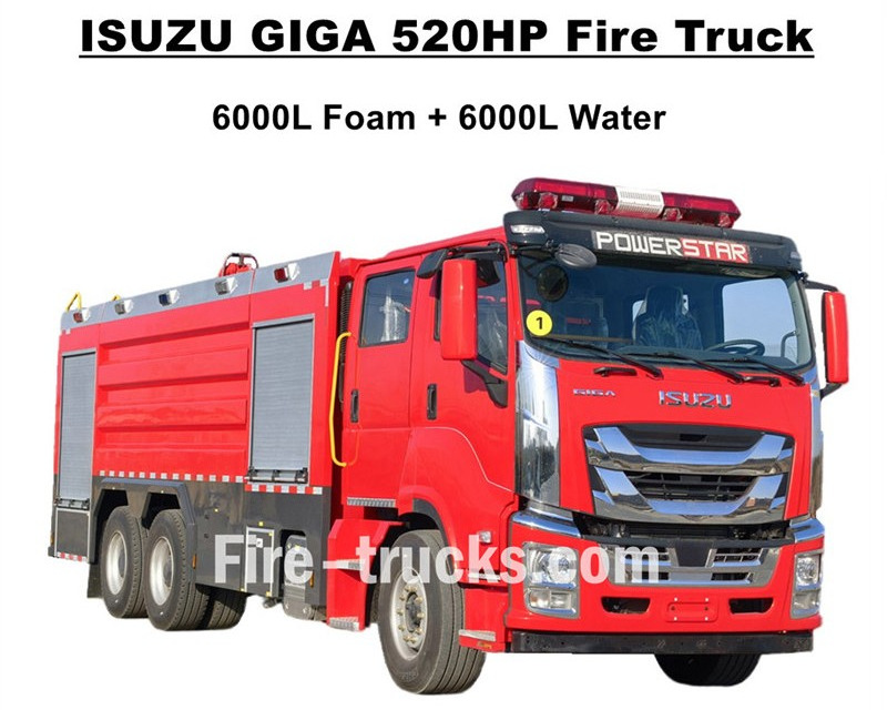
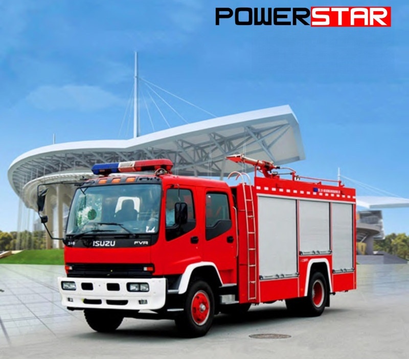
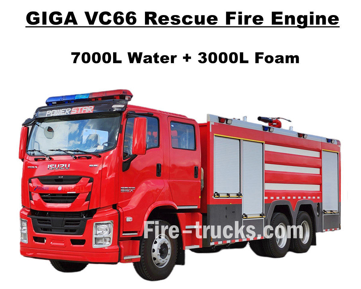
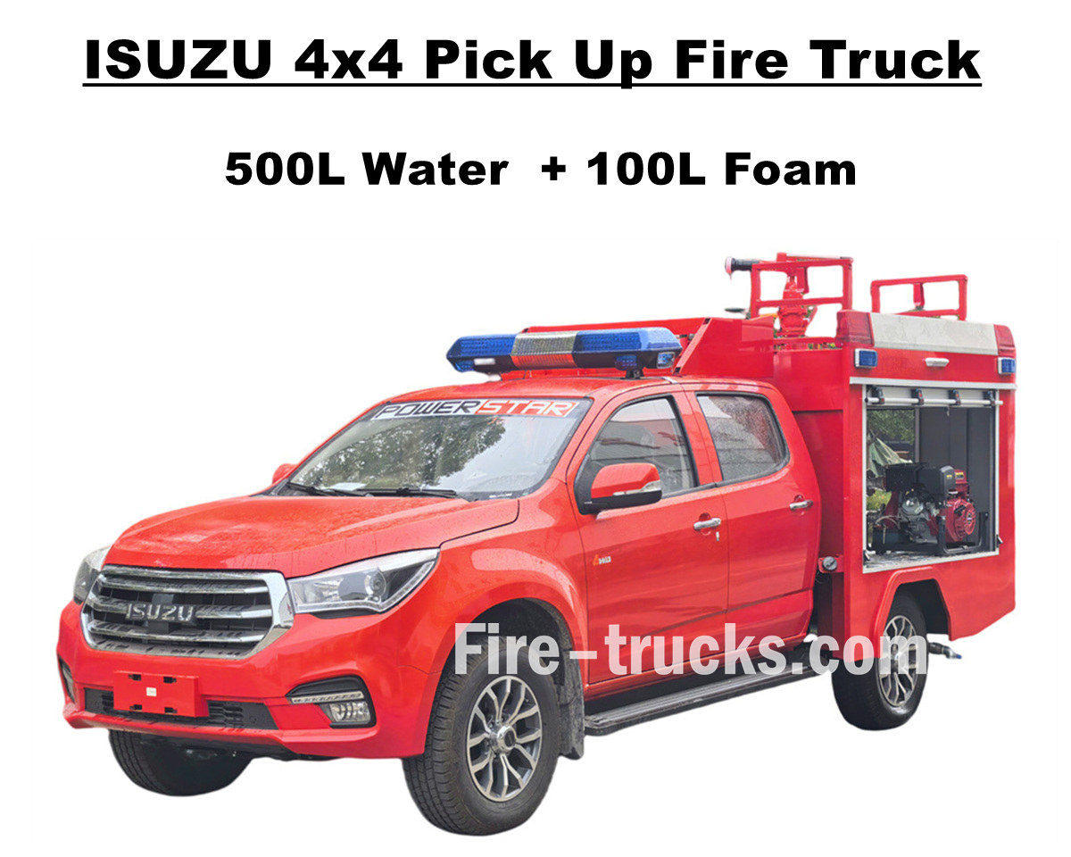
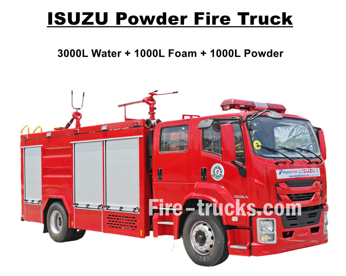

 IPv6 желісі қолдау көрсетіледі

 қазақ
қазақ English
 français
 Deutsch
 русский
 italiano
 español
 português
 Nederlands
 العربية
 日本語
日本語 한국의
한국의 Türkçe
 Melayu
 ไทย
ไทย Tiếng Việt
 Indonesia
  中文
中文 Filipino
 မြန်မာ
 српски